Yes. It remains to be seen whether it's better to separate the driver compensation from the crossover response, and design each separately, or to try to incorporate both into one overall filter design.
gberchin The way I have done it is to use what ever linear phase HP , BP or LP response I want as a target function and then generate the filter to achieve that target. Let D(w) = the river response and T(w) = the target. Then if F(w) is the filter defined, basically, as F(w) = T(w) / D(w). If D(w) for all the drivers is measured, say, relative to the baffle surface, then F(w) will include and excess phase due to acoustic offsets (relative to the baffle) automatically. F(w) is then emulated using FIR techniques.Hello,
What if the base filter is HP and not linear phase and we do an MDS using the pure delay ? Would you get the LPF output as usual ? I'm asking this because I do not seem to get anything that resembles an LPF, in either continuous (below) or discrete (post# 783) domain.
newvirus The problem with minimum phase high pass filters as the "base" is that the phase is nonlinear in the band pass. thus when you do the subtraction, F(w) = exp(jwTd)) - HP(w) there isn't a constant (or nearly zero) phase difference and you have frequencies where exp() and HP() are in phase and you get 1-1 = 0, a null, and other frequencies where they are 180 out of phase so you get 1- (-1) = 2 , a 6 dB peak. With a a minimum phase LP you have the same nonlinear phase but mostly in the stop band. The band pass of the LP is nearly linear phase (stress nearly) so the phase difference between the LP and exp() is small but starts to grow as the x-o frequency is approached. which gives the smooth roll off. (Note that if the LP section were truly linear phase and amplitude = 1 in the band pass the HP section would have a null response over that frequency range, not a smooth roll off.) As you move into the crossover region the phase of the LP section begins to rotate more rapidly which is why, in some cases there is a bump above 0 dB in the HP. Once into the stop band of the LP section the phase is less relevant because the amplitude of the LP is dropping off fast and you have (1 - a small number) regardless of the phase difference. Hope that helps.
I've found today's powerful processing and measurement allow such easy experimentation, and isolation of variables,Be careful, @mark100 , it is possible to have too much of a good thing.
that I don't have to guess about what to correct, and what degree of corrections to apply.
Just try it, measure and listen. And quickly and easily try some comparison. 🙂
FIR based, auto-acoustic target matching at the driver level, for multi-way DIY, is simply incredible, ime/imo.
And hard to do wrong, as long as some spatial averaging is used for the measurement to base correction off of, ....or better, polar verification of correction and xovers is performed.
Even inexpensive DSPs can support at least few 10s of biquads per channel across 6-8 channels, but that's not the point.
When too many filters are used, the quantisation and round-off errors are accentuated and accumulated, even with the most advanced processors. Every system has a limit on how small a number it can represent and the region below that (where everything suddenly falls to zero) is called a 'hole'. This is more or less like a black hole in outer space where everything beyond the event horizon simple "falls" to the singularity inside.
It is simply too much filtering, and probably best to minimise the same.
For the diy-end user with the delivered SW (I use Hypex and Minidsp) the practical rationale is to first eq each driver flat (within reasonable band and smoothing) and after that apply xo filters from the toolbox. After that set gains and delays. All based on acoustic measurements with single-channel USB-mic.
I aim mostly for LR2 or elliptic for 3/4-ways. Two-ways often require LR4 or other slopes. I use only IIR and manual settings.
I aim mostly for LR2 or elliptic for 3/4-ways. Two-ways often require LR4 or other slopes. I use only IIR and manual settings.
I though I'd make some comments on the subtractive delay filters and some insight when using linear phase and minimum phase base filters. If you think of the delayed input and the base filter as clocks with only one hand, then the length of the hand represents the magnitude and the position of the hand, 12, 1, 2,... the phase, then the input signal clock 's hand is a constant length of 1.0 and as the frequency rises it rotate at a constant rate. For the base filter, regardless of whether it's a high pass or low pass , when the base filter is minimum phase the clock initially rotates at the same rate as the input clock if the input delay is set to the DC GD of the base filter. However as the frequency increases toward the corner point of the base filter the rate of rotation changes and ultimately the clock of the base filter slows almost to a stop. Because of this the phase difference between the input clock and the base filter clock will alternate between 0 and 180 degrees and everything in between. Thus the frequency rises there can be peaks and valleys in the high frequency response of the derived filter. When the base filter is a LP filter these peak/valleys aren't too significant because the magnitude of the base filter is rolling off. But with a HP as the base filter the magnitude at high frequency is 1 thus the peaks and valleys become +6dB and nulls. One other thing to note is that for an LP base filter the phase is always 0 at DC. Fo a HP bass filter the phase is always 0 at infinity, and the phase at DC will depend on the order of the filter. Thus with a HP base filter, even with matched delay with the input, there can be a phase difference of 90, 180, 270,.... at DC. This doesn't much though because the amplitude of the base filter is small at low frequency. It's all abut what the phase rotate is at higher frequency.
On the other hand, if the base filter is linear phase and both the input and base filter have the same delay, both clock always rotate at the same rate and the amplitude of the derived filter is just a simple subtraction of the base filter amplitude form the unity input.
Below are some comparisons between using an LP or HP base filter with minimum phase and linear phase. The base filters had B2 amplitude response in all cased. Note the presents of ripples in the derived HP filter when using a minimum phase base LP filter. The dB scale 1dB/division. In all case, theoretically, the response sums HP + LP is flat, linear phase.
Even inexpensive DSPs can support at least few 10s of biquads per channel across 6-8 channels, but that's not the point.
When too many filters are used, the quantisation and round-off errors are accentuated and accumulated, even with the most advanced processors. Every system has a limit on how small a number it can represent and the region below that (where everything suddenly falls to zero) is called a 'hole'. This is more or less like a black hole in outer space where everything beyond the event horizon simple "falls" to the singularity inside.
It is simply too much filtering, and probably best to minimise the same.
yes, i've often read about the limits of precision inherent in biquad/IIR filters, and how they can behave differently given a specific processors.
It's been on of the talking points in IIR vs FIR discussions...how FIR in comparison doesn't suffer such.
Am also very familiar with the accepted wisdom of less EQ is often more EQ. I don't really expect that wisdom to be found lacking, but I do want to test it for myself.
Because as filter tools get better and better, who knows what caused the accepted wisdom to come to be....
its inherent truth, or the historical inability to perform precise fine tuning...
Anyway, I'm a try it and see kind of guy...so until I hear or measure degradation, I'll keep testing conventional wisdom.
It just doesn't pay to try to equalize every little peak and valley in the response. Beyond a certain point, it becomes more likely that you will just make things worse.It is simply too much filtering, and probably best to minimise the same.
I recall one time when I tried to EQ a small peak in the response of my speaker. I carefully measured that peak, and set a PEQ filter to exactly cancel it. It sounded awful. The problem was that I missed the center frequency by just a little bit, and the resulting phase shifts in the region of the peak made things sound like the ROBOT army had invaded, whenever the audio signal had content near that frequency.
Goodness gracious, a lot of discussion here.
If my two cents are worth anything,
I've always visualized phase response that crosses 180 degrees more easily if I imagine the graph wrapping around a tube.
If my two cents are worth anything,
Yes jcga, that is what i was saying, hoped was coming across
My point about ignoring group delay is that I simply think group delay is a very misleading, hard to work with measurement, compared to working directly with phase.
But in fairness, that's probably due to the fact I align linear phase driver sections, and flat phase traces of multiple drivers are very easy to see how to correct. All that is needed is the correct delays between drivers. (when using complementary linear phase xovers)
I can see however, if working with IIR and trying to tie phase curvatures/rotations together, that group delay could be more valuable....simply because it's harder to make sense of curved/rotated phase traces.
I've always visualized phase response that crosses 180 degrees more easily if I imagine the graph wrapping around a tube.
Aaarg...have to say, anecdotal evidence like this makes me cringe...It just doesn't pay to try to equalize every little peak and valley in the response. Beyond a certain point, it becomes more likely that you will just make things worse.
I recall one time when I tried to EQ a small peak in the response of my speaker. I carefully measured that peak, and set a PEQ filter to exactly cancel it. It sounded awful. The problem was that I missed the center frequency by just a little bit, and the resulting phase shifts in the region of the peak made things sound like the ROBOT army had invaded, whenever the audio signal had content near that frequency.
Who the heck hasn't heard an EQ misapplied???
And we can extrapolate a universal rule from our bad experience??? 🙂
Yeah: "Don't sweat the small stuff." 😉And we can extrapolate a universal rule from our bad experience?
It is common to use two or even three layers of filtering (channel, crossing, global etc.) but 256 filters is just too many and crazy ...Anyway, I'm a try it and see kind of guy...so until I hear or measure degradation, I'll keep testing conventional wisdom.
Apologies for responding to my own post, but @john k... , I just verified your statement in simulation (not that I doubted you, but I just had to see for myself). I'd say that this pretty much eliminates the problem of shallow HPF transition band slope. A 4th-order linear-phase Butterworth LPF, used in an MDS crossover configuration, produces a derived 8th-order HPF transition band slope. That should be adequate in all but the most extreme of situations.Your observation opens-up a whole new world of possibilities.
I fix big stuff, .......and small stuff too! ...🙂Yeah: "Don't sweat the small stuff." 😉
Because it's so easy to see if the small stuff has impact..
...and try to determine the line between big stuff and little,..... to determine best tuning practices and find what's really worth pursuing in terms of marginal impact.
It's seldom turns into sweat, ....it's fun..... I guess mainly because it's so easy to try things.
Can't say enough about modern open-architecture processors, FIR generators, and acoustic measuring software.
It is common to use two or even three layers of filtering (channel, crossing, global etc.) but 256 filters is just too many and crazy ...
Yeah, 256 filters is over the top for sure.
I just find it awesome that a task like that is so trivial for todays processors (which are basically just PCs of some form nowadays.)
For a driver's minimum phase flattening task, I've been comparing auto-IIR vs auto FIR.
Here's an example...a mid driver that I use varyingly between 200-900Hz in a synergy/MEH.
Raw response 1-24th smoothing Complex
200-900 Hz flattened with 32 IIR bi-quads, applied with 1-24th smoothing
Top panel shows the filter applied
Bottom processed mag and phase.
Same thing but filter applied via FIR
You can see the processed FIR is a wee bit cleaner, but not much at all.
If the number of IIR filters is cut, the comparison starts to degrade. How much of course just depends on what's needed to flatten raw response for any particular raw driver section.
Both strategies will measure acoustically just like their graphs show (for the given mic location)
Both will sound awesome.
Ime/imo, the idea that less EQ is often the best sound, is an anachronism. I think misapplied EQ's is the root of that incorrect idea.
IIR corrections are hard to match manually, given they way they interact with each other.
Todays tools do a great job of applying auto-EQ via FIR. A DIY godsend imho.
And it looks like auto-IIR is gaining traction for at least areas of flat response.
I have very little experience with auto-IIR, but if it can be made to work as well as FIR, I think it will be a home run.
That's a very good exercise to practise your manual EQing skills. Keep your pencils sharp, they say.Here's an example...200-900 Hz flattened with 32 IIR bi-quads, applied with 1-24th smoothing
That's a very good exercise to practise your manual EQing skills. Keep your pencils sharp, they say.
Been there, done that. Anachronisms die hard 😉
Excuse me, but why to eq so well just for a single mic position of a single speaker? 😎
Should the baseline measurement be done in an anechoic chamber or in a room, what distance, gating, smoothing?
My speakers at normal listening site, mic in hand near head, 2,5m from speakers.
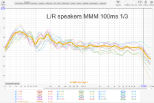
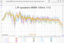
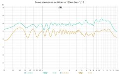
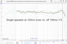
A single tall speaker in the middle of the room, mic 120cm away, design axis and 10 deg U/D, 15deg R
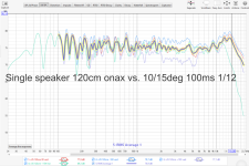
Should the baseline measurement be done in an anechoic chamber or in a room, what distance, gating, smoothing?
My speakers at normal listening site, mic in hand near head, 2,5m from speakers.


A single tall speaker in the middle of the room, mic 120cm away, design axis and 10 deg U/D, 15deg R


Last edited:
Excuse me, but why to eq so well just for a single mic position of a single speaker? 😎
It was just to show the ability of an auto-IRR generator when using a relatively high number of bi-quads (32), to produce FIR like flattening results,
No other purpose.
I used a single driver, at a single position....for sheer simplicity.
Well, we all have our methods.Should the baseline measurement be done in an anechoic chamber or in a room, what distance, gating, smoothing?
I prefer to use baseline measurements done as quasi anechoic as possible.
Best practice for me is outdoors, at about 3m...either off a deck with a long ground bounce, or ground plane on a driveway.
If indoors, I get as close as possible and still have a chance at being in the acoustic far-field.
Outdoors or in, I don't use gating. If reflections are a problem, I'd rather use frequency dependent windowing or a set number of period cycles.
Typically, i like to apply 1-24th smoothing to the baseline measurements that will be used to correct...and then play with varying degrees of smoothing on the applied corrections.
If a DIY build's driver sections raw polar responses looked well behaved, I'll often tune to a single-mic location a little off-axis, and then see how well processed polars hold up. If raw polars are struggling, I'll use spatial averaging to make a baseline for correction.
Here's a example of single-mic, single-spot, tuning of a 5-way syn/MEH made at 1m indoors.
Here's an outdoor set of polars made at 3m, 0-50 degree, of that indoor spot tuning.
Horn is a 90x75 so bottom 50 deg purple trace is outside horn
I don't make indoor listening position measurements. Everything sounds great based on prior quasi-anechoic work.
I do adjust variance in tracks tonality though, via real time levels controls of driver sections.
My bottom line...we do what works for us ! You seen happy with what you're doing too, congrats 🙂
Last edited:
@john k... , was this paper published? I'm updating my own paper and would like to cite yours. Thanks.I have attached a paper I wrote back in 2002 on the subject of SD filters based on linear phase base filters for those interested.
It was never published in a journal, just on my old web site. But the paper doesn't seem to be available there.anymore. You could reference it as a private communication, or, add a copy as an appendix to your paper, "with permission of the author".
http://web.archive.org/web/20040430163915/http://www.geocities.com/kreskovs/Digital-xoA.html
http://web.archive.org/web/20040430163915/http://www.geocities.com/kreskovs/Digital-xoA.html
- Home
- Loudspeakers
- Multi-Way
- Why not IIR filters + a global phase linearization by FIR
