Yes, the subtractive variant of an in-phase crossover that has an overall allpass characteristic can be done that way.It is easily realisable, just replace the "delay" with an all-pass filter of the same phase, frequency and q-factor of the highpass filter.
But those who want to use a constant voltage subtractive crossover wouldn't want to use an allpass like that because the motivation behind the classic subtractive crossover is transient accurary. And if you want to build an in-phase crossover you can also do it the usual way with seperate filter branches.
And yes, anything else than Linkwitz will be asymmetrical. But even these asymmetrical ones offer some advantages depending on use case.
But there are lots of possible compromises available with subtraction. I am using an asymmetrical crossover with a 3rd order highpass and a second order lowpass that has less group delay distortion than a LR2 for instance while offering steeper slopes and positive polarity on both branches.
Regards
Charles
Last edited:
I am very impressed with the creativity that the community has displayed in creating configurations for matched-delay subtractive crossovers. However, I feel the need to caution everyone against falling into the trap of designing entirely in the frequency domain.
At some point, DSP becomes "fun with numbers", and it becomes too easy to design "perfection" without regard to the consequences. Extremely steep filter transition bands are an example of this. The more "rectangular" the frequency response becomes, the more "sin(x)/x" the impulse response becomes -- that is to say, the more overshoot and ringing occur in the time domain.
How bad must the ringing be before it becomes audible? I just had an online discussion with one of the Major Contributors at Audio Science Review about exactly that question. The answer is:
1. Nobody knows for certain.
2. It is frequency-dependent.
3. Our tolerance for such ringing is actually quite large.
However, given that we exist in an audiophile world where people claim to be able to hear unmeasurable differences like the effect of the color of wire used as speaker interconnects, claiming that excessive ringing -- which is easily observed and measured -- is inaudible should give us pause. It is for this reason that all of my MDS designs seek to optimize transient response. You design for whatever pleases you, but be aware that nothing comes for free.

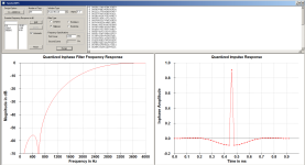
The 'word' delay seems to suggest something else other than the classic style subtraction. Now, even with a delay it is unlikely that the LPF would come out very well. For example, this is what I got (LR4) and as you can see the LPF is a total failure soon after the cutoff frequency. The phase matching between the delay line and the HPF is a must ..But those who want to use a constant voltage subtractive crossover wouldn't want to use an allpass like that because the motivation behind the classic subtractive crossover is transient accurary.
An analog or IIR lowpass has a more or less constant group-delay within its pas pand while the "constant" group-delay region of a higpass lies below its passband. It would certainly be nice if it was different. But sometimes the laws of physics don't like us
This is the crux. I know that HP filters are usually defined in terms of the frequency inversion of a LPF, as I already mentioned.Thank you, @phase_accurate , this is a point that needs to be made more often. It is the reason that, for example, a Bessel LPF has such a nice impulse response, while a Bessel HPF oscillates like crazy.
This is fine for a filter where the amplitude response as a function of frequency is the main criterium.
I think it's problematic for the Bessel, which is specified in terms of its group delay flatness for the LP.
Hence my idea for a HPF created to have maximally flat group delay in its pass band.
I think this is essentially what the Berchin implementation does.
I expect there is an equivalent continuous time HPF that could be directly implemented, rather than created as a sub-block from a subtractive filter, as in the Berchin implementation.
Hence my comment in post #777
'As far as I can see he adjusts only for the explicitly included delay blocks.
I don't understand how this would work in a simpler case, with an explicitly specified HPF.
I think it would need a filter defined to keep the group delay close to zero as far down as frequency decreases, presumably below the crossover point, like the inverse of an LP Bessel that tries to keep the group delay constant as far as possible as frequency increases.
Does that make sense and does such a filter exist or have a name?'
Still not sure if I have explained clearly?
I feel the need to caution everyone against falling into the trap of designing entirely in the frequency domain.
Yes, I think old, non-sampled, methods tend to focus on the frequency domain, sampled systems make it easier to think in terms of the time domain response, but they are different views of the same multi-dimensional mathematical "object".
I still can't quite visualize how they relate because I'm "old school", hence my interest in this thread to develop more familiarity in the time domain.
Best wishes
David
Last edited:
I am not very familiar with MATLAB or Octave, but I don't see that this is the maths for a subtractive crossover, either simple or with delay.If you follow MATLAB or Octave, here is the code. Hope that helps.
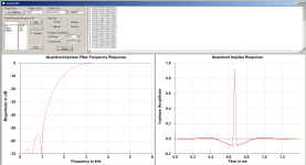
Code:% LOWPASS freq = 100; Q = 0.7071; wc = 2*pi*freq; % Cutoff frequency but_sys = tf([wc*wc],[1, wc/Q, wc*wc]); % analogue lowpass transfer function lp_sys = but_sys*but_sys; % BUT2 to LR4 %HIGHPASS freq = 100; Q = 0.7071; wc = 2*pi*freq; % Cutoff frequency but_sys = tf([1,0,0],[1, wc/Q, wc*wc]); % analogue lowpass transfer function hp_sys = but_sys*but_sys; % BUT2 to LR4 %ALLPASS (half-order, same Q) freq = 100; Q = 0.7071; wc = 2*pi*freq; % Cutoff frequency ap_sys = tf([1, -wc/Q, wc*wc],[1, wc/Q, wc*wc]); % analogue allpass transfer function % BODE PLOT DISPLAY options = bodeoptions; options.FreqUnits = 'Hz'; options.XLim = [1,20000]; options.YLim = [-360, 0]; options.grid = 'On'; options.Freqscale ='Log'; %options.MagVisible = 'Off'; options.PhaseWrapping = 'Off'; options.PhaseMatching = 'On'; figure(1) bode(hp_sys,ap_sys-hp_sys,options);
Happy to learn more if I am mistaken.
Best wishes
David.
I am very impressed with the creativity that the community has displayed in creating configurations for matched-delay subtractive crossovers. However, I feel the need to caution everyone against falling into the trap of designing entirely in the frequency domain.
At some point, DSP becomes "fun with numbers", and it becomes too easy to design "perfection" without regard to the consequences. Extremely steep filter transition bands are an example of this. The more "rectangular" the frequency response becomes, the more "sin(x)/x" the impulse response becomes -- that is to say, the more overshoot and ringing occur in the time domain.
How bad must the ringing be before it becomes audible? I just had an online discussion with one of the Major Contributors at Audio Science Review about exactly that question. The answer is:
1. Nobody knows for certain.
2. It is frequency-dependent.
3. Our tolerance for such ringing is actually quite large.
However, given that we exist in an audiophile world where people claim to be able to hear unmeasurable differences like the effect of the color of wire used as speaker interconnects, claiming that excessive ringing -- which is easily observed and measured -- is inaudible should give us pause. It is for this reason that all of my MDS designs seek to optimize transient response. You design for whatever pleases you, but be aware that nothing comes for free.
You're doing the Lord's work.
A couple of jobs ago the chief engineer wanted some lowpass filters so codecs could have an easier time. However, the transition band from corner frequency to maximum attenuation was spec'd at 1 kHz wide for filters at 10, 12, and 15 kHz. Mm-kayyyyy... The design tool gave me filters as desired (ScopeFIR for the win), which of course had massive pre- and post- ringing. I coded them up in the DSPs and listened.
They sounded horrible! Music with any high frequency content such as cymbals or high-hats was like having a hatpin scraping away at my eardrum. I asked the chief to let me widen the transition bands, and while the problem didn't entirely go away at least I didn't feel like throwing my Sennheiser 580s against the wall.
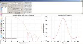
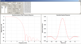
Now here are the filters I like to use. The first pair are tweeter highpass and mid lowpass at 2200 Hz with gentle slopes. Note there is only one sidelobe on either side of the central lobe, which is about as small as a usable filter can get. The second pair have two sidelobes on either side of the center. The second filter pair has slightly higher sidelobe energy, although still considerably lower than the main lobe energy. In any case the lowpass and highpass filters sum to a single peak in the time domain, as one would expect for a system flat in amplitude and phase response. Either set is fine for crossovers, although the second pair has considerably less out of band energy to the drivers, which might be important for tweeters and mid drivers with resonances out there.
Attachments
.. I don't see that this is the maths for a subtractive crossover.... with delay...
Why not? The last line obtains the LPF by subtraction of the HPF from the APF (with same GD as the HPF).
bode(hp_sys, ap_sys - hp_sys, options);
As far as I understand, the allpass is the best delay line you can implement in the s-domain. Please see link for the scope of a pure delay.Happy to learn more if I am mistaken.
https://lpsa.swarthmore.edu/BackGround/TimeDelay/TimeDelay.html
And welcome to z-domain !!
In simple terms: If there was one like that, transient-perfect speakers using analog crossovers would be a no-brainer.I expect there is an equivalent continuous time HPF that could be directly implemented, rather than created as a sub-block from a subtractive filter, as in the Berchin implementation.
Could you explain a little further ?Hence my idea for a HPF created to have maximally flat group delay in its pass band.
Would you also be satisfied if the crossover as a whole has a flat group-delay characteristic and not just the highpass ? What is a flat group-delay characteristic in terms of your expectations ? Constant group-delay ? The lowest average group-delay possible ? A group-delay characteristic without peak(s) ?
Depending on your need there might even exist a not-too-complicated analog solution.
Regards
Charles
It has a subtraction, but the term is usually used for a transient perfect subtractive crossover, where the subtraction is from the inputWhy not? The last line obtains the LPF by subtraction of the HPF from the APF (with same GD as the HPF).
bode(hp_sys, ap_sys - hp_sys, options);
1 - hp_sys
to produce outputs that sum exactly to the input.
not
ap_sys - hp_sys
that sums to an all-pass response identical to a standard Linkwitz-Riley crossover. In which case may as well use the standard LR.
But thank you for the demo, I think I need to download Octave.
Best wishes
David
Last edited:
Haha! ... Well, I hope that the Lord has more important things to worry about than filter impulse responses, but thank you just the same!You're doing the Lord's work.
"Fun with numbers!"The design tool gave me filters as desired ...
See, that's where everything gets confusing. As I mentioned above, I discussed this with one of the "Major Contributors" at ASR. For fear of name-dropping I won't mention his name, but he is one of the acknowledged world experts on audio masking, audibility, etc. (I know him from work he, I, and others did on the original MPEG-1 audio, way back in the early 1990s.) According to him, our hearing is far more tolerant of pre- and post-ringing than I ever imagined, so even the extreme situation that you described should be, at most, minimally audible.They sounded horrible!
I ended my discussion with him by saying that I will stay with my original goal: minimization of all ringing -- at least until such time as the audibility of ringing is better characterized.
Obscure fact: analog transversal filters, implemented with analog delay lines, do exist.As far as I understand, the allpass is the best delay line you can implement in the s-domain.
https://dsp.stackexchange.com/questions/34726/fir-analog-low-pass-filter
Actually, I did expect a post saying something like this, but from phase_accurate instead !Obscure fact: analog transversal filters, implemented with analog delay lines, do exist.
Sorry, but that was not what you asked for -It has a subtraction, but the term is usually used for a transient perfect subtractive crossover, where the subtraction is from the input
1 - hp_sys
to produce outputs that sum exactly to the input.
Dave Zan said:"So my first idea was to define the HPF, add a time adjustment to the input and subtract to produce the LP, just the dual of the standard version.
The time adjustment would be the group delay of the HPF, just as in the the canonical version it's the delay of the LPF.
But the group delay of the HPF is not a "delay", and decreases towards zero, so I'm not sure it's realizable."
For the case that uses a true delay, see post #783, and Linkwitz Riley shouldn't matter much, as Bessel would give more or less similar results. I had tried gberchin's method in a previous post and if I remember correctly, he squares the derived response before the next subtraction from a double delay and so maybe you can also try something like that to see if it would work for the HPF-based MDS as well.
Dave Zan said:"The dual of Lipshitz & Vanderkooy, similar to Berchin's but continuous time."
Not sure if that's the way to go, but downloading Octave should definitely be a good start nevertheless.
Here is a good thread containing discussion about the audibility of phase with some user names that ring a bellAs I mentioned above, I discussed this with one of the "Major Contributors" at ASR. For fear of name-dropping I won't mention his name, but he is one of the acknowledged world experts on audio masking, audibility, etc. (I know him from work he, I, and others did on the original MPEG-1 audio, way back in the early 1990s.) According to him, our hearing is far more tolerant of pre- and post-ringing than I ever imagined, so even the extreme situation that you described should be, at most, minimally audible.
https://www.audiosciencereview.com/...n-shift-matter-in-audio-no.24026/post-2113610
(Shhhh) ... yes, that would be the one.Here is a good thread containing discussion about the audibility of phase with some user names that ring a bell
Would you also be satisfied if the crossover as a whole has a flat group-delay characteristic and not just the highpass ? What is a flat group-delay characteristic in terms of your expectations ? Constant group-delay ? The lowest average group-delay possible ? A group-delay characteristic without peak(s) ?
Hi Charles, great questions.
Group-delay...sigh and yikes...
Maybe you can help me understand why folks focus on GD, when DIYing speakers.
Seems to me GD is just an abstraction/distraction from the two real underlying variables, fixed time and phase.
And frankly, for me GD seems a bit worthless to focus on, compared to focusing directly on constant time and phase.
Here's why. Seems that the formal definition of group-delay has two basic components:
First being simple constant time delay that doesn't vary by frequency.
And second being frequency dependent phase rotations mapped into frequency dependent GD "pseudo time".
For speaker building purposes:
Fixed-time delay is needed for geometric time-of-flight offsets of acoustic centers, or differences in channels' processing latencies, etc.
No other valid use of constant-time delay which doesn't vary by frequency come to mind (and there's no substitute for constant time either).
Frequency-dependent "pseudo time" GD is simply an unwanted bastard, ime/imo.
The "time" difference in GD, between its flat low-frequency plateau and its flat high-frequency plateau, around the filter's transition region,
is not real time and can't be used as a substitute for proper fixed time delay.
So it has no real value for any useful purpose. (evil idea, that pseudo time, lol)
The transition region, where the phase rotation lies, blesses us with envelope distortion...hence the unwanted bastard.
Bottom line for speaker building imo:
I say simply use constant-time delays to solve constant-time alignment issues (and quit thinking of constant-time as part of GD.)
And simply minimize phase rotations, by working directly with phase. (and quit thinking of GD at all !!)
Why even consider GD?
They sounded horrible! Music with any high frequency content such as cymbals or high-hats was like having a hatpin scraping away at my eardrum. I asked the chief to let me widen the transition bands, and while the problem didn't entirely go away at least I didn't feel like throwing my Sennheiser 580s against the wall.
Something sounds amiss. Given sufficient taps, and truly complementary xovers, my experience is virtually any order lin phase xover can be used without audible effect. It appears the xovers shown are lin-phase??
I'd think this would be especially true for head phone use????
GD doesen't have a purpose as such but it is a property. Since not everyone wants to user FIR crossovers (or and DSP or computer at all) there are cases where one has to live with it and make the best out of it.So it has no real value for any useful purpose. (evil idea, that pseudo time, lol)
The transition region, where the phase rotation lies, blesses us with envelope distortion...hence the unwanted bastard.
Thank Charles, my question was meant to be more of a historical type question, as in how did GD ever become an important property in DIY.
(or maybe it was just my personal Freudian rant lol)
Whether it's folks modeling passives or IIR via analog/digital, .... in Vcad, xsim, whatever xover/filter program,... GD appears gets a lot of attention.
I just can't see why. It's worthless imo.
I suspect the attention may be that GD was sometimes advocated in the past as a usable form of constant delay.
Something sounds amiss. Given sufficient taps, and truly complementary xovers, my experience is virtually any order lin phase xover can be used without audible effect. It appears the xovers shown are lin-phase??
I'd think this would be especially true for head phone use????
Remember the aforementioned horrid filters were lowpass filters with lots of ringing, not crossovers. The crossover filters shown in the pictures are much shorter, which helps considerably with off-axis response when driver radiation tends to fall out of phase alignment so sidelobes would not cancel completely. Under those conditions ringing could make an appearance, hence my preference for shorter impulse responses as crossovers. Note the example rolloff characteristics are not a million dB/octave: the gentle slope is about the same as a 4th order Linkwitz-Riley, and the steeper one is closer to 6th or 7th order. Why not use standard filters if the attenuation is attainable by those? The answer is linear phase: I prefer unrotated phase response until slightly over 2 kHz or so. The literature says phase can be detected below about 1350 Hz or so, undetectable beyond 1500 Hz, but I like to err on the side of caution.
The crossover filters shown in the pictures are much shorter, which helps considerably with off-axis response when driver radiation tends to fall out of phase alignment so sidelobes would not cancel completely.
Yes, I know that having shorter filters with lower orders helps to reduce the potential for off-axis sidelobe summations not canceling completely.
Good strategy I think.
An alternative I've come to like, is to go ahead and use longer filters with higher orders, being willing to accept pre-ring potential in exchange for limiting the width of acoustic lobing regions.
I figure not only does the potential for pre-ring decrease due to being confined to narrower critical crossover regions,
but also ordinary acoustic lobing decreases due to keeping more of the full critical crossover region within tight c2c spacing.
So a double win for steep complementary linear-phase xovers, albeit at the expense of perhaps audible, perhaps not, pre-ring potential.
Sure thing. But why not standard complementary linear-phase filters, like simple LR's?Why not use standard filters if the attenuation is attainable by those? The answer is linear phase:
Yep, that's my take on phase audibility too. Seems recent research is leaning towards the lower the frequency, the more likely the audibility.I prefer unrotated phase response until slightly over 2 kHz or so. The literature says phase can be detected below about 1350 Hz or so, undetectable beyond 1500 Hz, but I like to err on the side of caution.
- Home
- Loudspeakers
- Multi-Way
- Why not IIR filters + a global phase linearization by FIR