I don't think that on youtube there is much more possible than short checking. You won't get a close contact to this kind of music with youtube. Too bad quality, its even more bad than MP4. For this, you need the real stuff, not the hifi-ish stuff. Classical music just sounded good on the best equipment, not the bad ones. At least thats my feelings about this highly complex orchestral music.
Schmitz77,
it can serve very well as an introduction to this astounding piece of music, nicely performed according to myself, unlike some versions I have on vinyl and CD with more venerable participants, indicating a high level of education.
Well, you know, the internet is a source for all kinds of false information.
To learn, what is correct and what is a false used term doesn't work with the internet. You can't even google it, you will receive onehundretthousand answers.
But you can read a book of whisdom. It will tell you.
LMAO Horses*it. There are PLENTY of accredited scientific resources online. That's why nobody buys a set of f*cking encycopedias anymore.
I'll take your word for it - I read what you said on the internet so it much be wrong.
The inherent trouble with the internet is.... you often times don't know who wrote about a certain subject, and what their background, education, or certifications are.
For all it matters, some annonymous snotnose 14 year old kid with big (and stupid) ideas wrote something, and people would believe his nonsense.
And that at times could be dangerous to others.
It's like all the fake news being pushed on the masses, you gotta use common sense and ignore it.
I've seen this, I'm sure others have as well.
Thankfully, being a professionally trained technician, I can easily spot such misinformation and either ignore it, and/or call it out for what it is.. internet BS.
As to the title of this thread "Why has Single ended become popular". I'll give everyone my two cents..
SE amps are overhyped for what they are, and in my opinion, are not "hifi".
I don't give two hoots what others may reply about that comment, so they can save their retailation for someone else.
In my belief, high fidelity requires efficient power, and implimented in such a way as to reduce distortions below what normal people can detect, and that IMO is what a PP amp can easily provide.
PP easily allows for the dynamic levels needed for serious listening.
An inefficient SE design produces substantial amount of wasted power/heat, along with its properties of distortion levels that need rectifying in order to get to a reasonable listenable condition.
You can have all that BS, not my cup of tea.
Well, if that was a Bohemian point of view, I'd be interested to hear a conservative point of view.....
It is true that a solid technical background is required to shift BS from truely helpfull info. But SE amps can deliver a homogeneous audio experience, and yes, we do not care about efficiency if it comes to getting the magic we seek for.
Talking about efficiency.. we just went to Mars 3 times....
Enough said...,
Talking about efficiency.. we just went to Mars 3 times....
Enough said...,
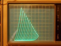
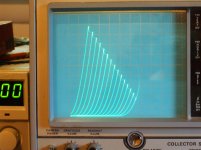
Here is a 6HJ5 TV Sweep using "new" series Schade (UnSet, CED at Tubelab).
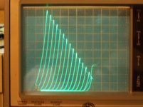
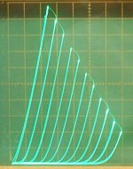
2nd pic is the 6HJ5 using conventional internal triode mode. (with typical high triode plate curve rollover of Sweeps)
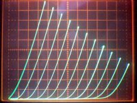
3rd pic is a 211 DHT (rollover mostly gone)
DHT typically gets rid of most of the plate curve rollover. Reducing 2nd harmonic dist. greatly. The latest series Schade, UnSet, CED can do it too. (and 1/2 an Amp at top of the screen)
2nd pic is the 6HJ5 using conventional internal triode mode. (with typical high triode plate curve rollover of Sweeps)
3rd pic is a 211 DHT (rollover mostly gone)
DHT typically gets rid of most of the plate curve rollover. Reducing 2nd harmonic dist. greatly. The latest series Schade, UnSet, CED can do it too. (and 1/2 an Amp at top of the screen)
Attachments

Last edited:
Getting back to the "soul" and "magic" SE amplification can and I assume, for some designs, from some listeners, does actually invoke...
What's the source of this invocation one can get out of a particular arrangement of electrical components?
I was hoping it had something to do with the magnetics, but I see no deliberate inclusion of magnetic components in SE design - unless you have to - to make the arrangement of parts convey magic and soul. So what is it, then?
The non reversal of electric current? Of electrostatic and magnetic polarizations? Those micro-modulations stand up much better within a continuous flow, than one which has to stop and reverse? Or is it as much circuit simplicity as non electron flow reversals that's the "key"?
Has anyone designed a dynamic speaker this way? Deliberately make a "sagging cone" so you must provide DC bias to pull the VC into a centered gap position - so you have class a - all the way to the VC motor?
When I was a youngster (say, 1970), I had an xtal breadboard radio that drove headphones. I built a single transistor amp from some RS handbook, which put enough DC bias current through the speaker that it pulled the cone out of its centered position. I didnt know enough about electronics to fix it, but I was interested - because it sounded funny - even better - with it pulled back like that, but I knew that's not how it was supposed to be. Enough interest to discover (as a kid on a bicycle) that 1960's GM car radios used an autotransformer to help with that. Even once saw a stereo one with two autotransformers. Your '60's stock car radio was likely class a amplification.
Dunno about 60s, that was advent of transistors. 50s, especially more upscale cars, used PP. 6AQ5 was a 6V6 specifically adapted (miniaturized) for car use.
Earlier car had SE in their radios. I have 1937 Plymouth with optional Philco AM radio. It is SE, with 43 output tube, if I remember correct. Sounds pretty good.
A speaker with DC coil preload will have increased 2H distortion because of asymmetry.
Earlier car had SE in their radios. I have 1937 Plymouth with optional Philco AM radio. It is SE, with 43 output tube, if I remember correct. Sounds pretty good.
A speaker with DC coil preload will have increased 2H distortion because of asymmetry.
Smoking amp, could you please explain what do you mean by "rollover"? I am looking at the graphs and don't see any big, striking difference.
Why would you bother making a so called class A speaker when speakers aren't limited to one direction for current flow?
1st pic, is a series Schade corrected Sweep curve set adjusted for near to no roll-over (over adjusted a little actually). 2nd pic is a DHT with naturally low roll-over. 3rd pic is high roll-over (actually the same tube as the 1st pic, but without the heavy roll-over correction).
4th pic is the previous posted series Schade 6HJ5 curves, with modest correction.
5th pic is same 6HJ5 with no corr.
6th pic is a frame grid video tube with naturally low roll-over
7th pic is the 211 DHT curve set with low roll-over
Roll-over refers to the triode curves at the HV end having a higher Ri, making them appear to roll-over to the right. Just compare the 0 Vg curve on the left with the rightmost curve. Are they identical? Usually not. The roll-over effect causes 2nd harmonic crowding of the curves on any load line drawn. DHT tubes have less, IDH ones usually more. CED/UnSET can fix them.
Attachments


Last edited:
Hello v4lve lover, would you please elaborate ? I have a large stash of PL36 and have found a few schematics, but the opinion are divergent about them. Have you actually built something with them ? SE or PP ?
thanks !
Charles
The EL36/PL36 was re-rolled into E235L its the same tube just a standard EL34 pinout as opposed to the topcap 36
Would it matter if i said i built something with them? Im the great oddball that builds tube amplifiers with tube regulated B+ ive only seen a few dozen amplifiers that do this... Cause its all people parroting others. If you really want something nice get some nice good bandwith high inductance output transformers. And build a tube regulated supply for the B+
I have a theory that most tube amplifiers sound different because the output stage reacts with the high Z tube rectified supply. I was talking to an Old gentleman that was in jukebox amplifiers all his life, and he made the analogy that part of the dynamic was because supply impedance is like a string that gets pulled with the music.
a good tube regulated supply is a heavy handed approach to getting say: 0.5Ohm output impedance on your supply. In class A it hardly matters what the regulator does, class B is more tricky because you need a lot of headroom to provide uber stiff supplies.
Ive used them in regulators and cathode followers, Sonic comparisons on this. forum are usually apples and oranges anyway different transformers. different working points. And most of the SET designs don’t account for the variance in tubes at all..
The enjoyment of DIY is the fact that you built it yourself. You shouldnt get hung up on what part number the tube is: If someone wants me to design with particular tubes because “they sound nice” its the end of the conversation
Last edited:
1st pic, is a series Schade corrected Sweep curve set adjusted for near to no roll-over (over adjusted a little actually). 2nd pic is a DHT with naturally low roll-over. 3rd pic is high roll-over (actually the same tube as the 1st pic, but without the heavy roll-over correction).
4th pic is the previous posted series Schade 6HJ5 curves, with modest correction.
5th pic is same 6HJ5 with no corr.
6th pic is a frame grid video tube with naturally low roll-over
7th pic is the 211 DHT curve set with low roll-over
Roll-over refers to the triode curves at the HV end having a higher Ri, making them appear to roll-over to the right. Just compare the 0 Vg curve on the left with the rightmost curve. Are they identical? Usually not. The roll-over effect causes 2nd harmonic crowding of the curves on any load line drawn. DHT tubes have less, IDH ones usually more. CED/UnSET can fix them.
Those curves are shot on a tektronix 576? That is the mercedes benz of curve tracers.
You shouldnt get me wrong, this is not criticism but meant to be constructive.
SOME of the artefacts you see have to do with the way the sweep is generated in that machine. The step generator is a pulse integrator, that abuses some logic gates to make a zero crossing comparator for synchronizing the sweep with the staircase generator for the grid sweep. this is eventually fed into a pulse integrator, and this pulse integrator shifts somewhat. If you look at the manual you may see in the scope pictures of the schematic of the staircase generator that show the steps are not quite horizontal but have a very very small incline to them. This has to do with leakage current in the integrator stage of the machine, and i think if you douse the entire staircase generator board in IPA you can lower the leakage somewhat.
The anode sweep consists of pulsating AC so each curve is written twice, because there is no cut off at the peak of each sine so its not a sawtooth shape. If the grid shifts somewhat and the phosphorous dot walks back over the screen this will cause artefacts on the display. I think this causes some of the differences you see in your comparison between Directly and indirectly heated triodes. Because simply put the indirectly heated tubes you mention have WAY higher transconductance and MU. If you use the series resistance bank in the 576 this effect will be WAY more pronounced in indirectly heated tubes, because of higher MU and Transconductance.
The 577 is the cheaper, simplified version of the 576 because the latter was too expensive for companies to afford. It uses to matched NPN BJT pairs for the zero crossing comparator. Sometime ago i wanted to build my own tube curve tracer that used two floating high side current sense amplifiers to take the IA readings of two tubes simultaneously. So you could overlay these on a simple analog scope in XY mode. I actually made fixtures for testing two tubes simultaneously.
Last edited:
You may be describing the TEK 577 or 575 step generator. (using a pulse generator and integrator)
The 576 uses a D/A converter fed from a digital counter (ICs) followed by a high speed step amplifier with Neg Fdbk. The digital chips have also been changed from 7400 series TTL to 74LS00 TTL, and the counter logic race condition fixed with a 74LS132 in place of the 7400.
I became thoroughly familiar with the 576 after making extensive mods to it for doing tube curve tracing. This model can now do stepping up to +/- 172V versus the original +/- 20V. It also does 15 curves max now instead of 10 for the original. It now uses high speed HV transistors for the step amplifier as well.
The plate voltage sweep can be selected for either either half wave 60 Hz (in either direction with blanked retrace) or full wave 60 Hz sweep. So plate sweep voltage can be done with either 0 to Vmax or Vmax to 0 or both. It can even display tube pentode knee hysteresis by switching the sweep direction for both ways and using an odd number of traces.
I -have- seen some tube datasheets where every other plate curve is shifted a little, giving the appearance of "twinned" plate curves . This could be due to the type of step pulse generator you described. In the 576 tracer there is a comparator adjustment to center the step triggering from the 60 Hz sine wave to get equal spaced traces, and it can be checked easily by selecting between half wave and full wave sweeps. The load resistor can also be selected for value via the max power limit.
The 576 is rock stable, with regulated power supplies for everything internal.
And it weighs a ton from the large xfmrs used to supply all voltages including the HV plate V sweeps. The typical tubes tested here only draw a fraction of the 220 Watt power rating for SS devices it was designed for. The highest 1500 V sweep has also been modded to 750V at 2x current rating for a better and safer match to the tubes tested, although I usually use the 400V max scale.
I am confident the differences between DHT curves and IDH curves are real. And the series Schade / CED / UnSET can smoothly correct the difference.
The video tube posted above ( 6th pic) with DHT like curves has a gm rating of 21000, so that would dispel any connection between tube gm versus curve shape.
Series Schade / CED / UnSET also works well with the lower gm 6L6-oid tubes to fix triode curves.
The cause of plate curve "roll-over" is well known. The later tube designs pushed for more gm with the advent of Neg. Fdbk that could make use of it. This generally led to grid 1 wires being placed closer to the cathode, causing wire proximity effects, called island effect or inselbildung as described in Deketh's book or Spangenberg's book.
Last edited:
Absolutely my position. If ever someone without an excellent technical background hears something especially sounding, they claim its because this concept or that, but most often thats nonsense.As to the title of this thread "Why has Single ended become popular". I'll give everyone my two cents..
SE amps are overhyped for what they are, and in my opinion, are not "hifi".
I don't give two hoots what others may reply about that comment, so they can save their retailation for someone else.
In my belief, high fidelity requires efficient power, and implimented in such a way as to reduce distortions below what normal people can detect, and that IMO is what a PP amp can easily provide.
PP easily allows for the dynamic levels needed for serious listening.
An inefficient SE design produces substantial amount of wasted power/heat, along with its properties of distortion levels that need rectifying in order to get to a reasonable listenable condition.
You can have all that BS, not my cup of tea.
There are always good and bad designs, and the problem with the bad designs are, they appear in every price class, even in the high end. But if you are DIY, no market can drive you into bankruptcy.
Anyone who wants to overcome inferiority and realize better things for themselves has to open up their own hi-fi world. It only goes on with enthusiasm, it gets better. Better? And how! Much better! Enthusiasm sets you free! For the enthusiastic enthusiast there is no such thing as "too expensive", no "too rare", no "too difficult to obtain", no "not worthwhile, the market is too narrow". Any restriction that is important in commerce falls flat. There is no compulsion to survive in the market.
We could build what we wanted, we could think about a problem as long as we wanted, and we made unrestrained use of this freedom. The commercial designs has to ..... But we! We can! But we can also let it stay - and often enough we have let it stay; we are allowed to, and we took advantage of it so shamelessly that a business graduate would foam at the mouth - nothing can drive us into bankruptcy. The best is just good enough.
The hi-fi industry claims this often enough, but it is prescribed by the marketing department. There are power amplifiers on the market for tens of thousands of euros, where 500 euros for the power tubes were already too much money, too expensive. Of course nobody says that. The advertising prefers to speak of "manufactured according to our own specifications and strictly selected".
And with such a tube amp, it doesn't matters if its SE or PP designed. Both are sounding exceptional good. Its just a matter of excellence, how its technically done.
Last edited:
Indeed, is this rollover difference between IDHT and DHT independent of mu and gm? Those sweep tubes tend to be higher mu than true DH triodes.
I became thoroughly familiar with the 576 after making extensive mods to it for doing tube curve tracing. This model can now do stepping up to +/- 172V versus the original +/- 20V. It also does 15 curves max now instead of 10 for the original. It now uses high speed HV transistors for the step amplifier as well. .
You Know your stuff, thanks for taking the time to do a write-up very informative. Ive bookmarked the page for reference.
I assume you know enough about TTL to use them from approximately the same decade? But that's besides the point, now im really interested in the circuit you have used for the step amplifier as the buffer i wanted to use at the time was based on the one in AN18F but maxed out at 15Khz or so.
Spangenberg 1948 describes the situation classically, and his 1957 _Fundamentals of Electron Devices_ chapter 15 is a big improvement over RDH4 (IMO) for its discussion of non-linear effects.
I'm a big fan of type 211 but wouldn't believe GE's curves without testing. Curves in those days were drawn with French curves and sketched in the parts that "didn't matter". Call me cynical; just don't call me late for dinner.
A different issue is whether or not you should be operating down there anywho. This is DIY; pick a better spot for your picnic. Just another opinion.
YOS,
Chris
The cause of plate curve "roll-over" is well known. The later tube designs pushed for more gm with the advent of Neg. Fdbk that could make use of it.
This generally led to grid 1 wires being placed closer to the cathode, causing wire proximity effects, called island effect or inselbildung as described in Deketh's book or Spangenberg's book. It gives grid 1 something like a square law transfer function, versus grid 2 with a 3/2 power transfer function. As the current varies, the two different power laws mis-track. Causing variation of the internal grid 1 / grid 2 Mu factor and consequent variation of Ri seen as "roll-over".
The TV Sweep tubes generally have an internal Mu of 3.2 up to 4.2, so are right in the same range as the power DHT tubes used for SET. But the gm of grid1 and grid 2 are both increased significantly over DH tubes. Gm per se is not the problem, if the grid wire pitch is shrunk by an equally appropriate amount to match the closer cathode spacing. But Neg. Fdbk coming on the scene allowed for sloppier tube construction, more gm could just fix it using the N Fdbk. Fewer grid wires than needed for linearity allowed higher current, for more power.
---------
The new step amplifier uses 250V MJE15032G to 260V MJL3281A topside, and MJE15033G to MJL1302A bottom side for a complementary Darlington output stage. For 350V one could go to MJE15034, MJL 4281A and MJE 15035 , MJL4302A for the step amplifier. I put some 0.51 Ohm emitter resistors under the MJL emitter outputs for biasing ease. Then some 51 Ohm resistors between top and bottom side MJL bases, center connected to output/emitters. The MJE bases have a dual Si diode series bias (each side) with 10 uF bypass caps to the center input V. These produce a very slight crossover glitch intentionally, so I can see when the 0V stepping output is being crossed for calibration, and prevents cross current run-away in the amplifier. Then 130K pull up/down resistors from the MJE bases to the + and - supplies at the respective collectors.
The TEK 576 allows both + and - stepping crossover in one sequence, with 20V in one direction and (now) 172V in the other direction (depends on the setting of the 0V offset control, a ten turn pot) and the polarity relay. Several other limit diodes and caps around the step amplifier get up rated to the higher V as well.
There is a relay in the step amplifier power input that switches the polarity of the supplies for + or - stepping. Going too far with up rating the step voltage range/supply could cause arcing across those contacts. DC arcing being hard to break, so don't switch stepping polarity while actively tracing. I checked, the relay is not contact rated for 170V + 20V, but it works. The relay is in a socket, so I left it as is. Spare on hand.
Last edited:
- Home
- Amplifiers
- Tubes / Valves
- Why has single ended output become popular