Disabled Account
Joined 2003
What is "wrong" or "right" with the ProAc's is due to that ProAc design.
Troels merely offers an alternative for a more neutral (accurate) SPL vs frequency response, whilst maintaing 3Khz 3rd order electrical slopes. If this robs the speaker of it's 'sparkle, magic, musicality or [insert vague magazine reviewer adjective] here, by all means you can stick with the original speakers (US$4,500) or original www.geocities.com/diyproac25 clones.
We can all theorise as much as we want as to what exactly is wrong with waltona's wilmslows, give testimonials as to other wilmslow speakers, or make assumptions on Troel's original designs (8545/9500 Amish) based on crossover mods he made for a clone of a commercial speakers, but without real well-made near and far field measurements of waltona's wilmslows, it's all speculation and trial and error from here.
5th Element said
3dB is TWICE the acoustic power and is VERY significant. The same difference as 100W amplifier to a 50W amplifier, or two woofers to one.
Dave S:
Comparing two different speakers in different rooms and systems is worth about 0.01 cents in my book. The SAME speakers, can sound markedly different in different rooms and systems IME.
Broad sweeping statements Troels designs based his re-work of the clone crossover, is unfair IMHO. As many several measurements have shown, there are several factors that suggest that 8535 and particularly 8513 are not really suited to a 3Khz crossover point. The 8535 is a great driver below 2Khz, and that small 3/4" 8513 dome is best above 4-5Khz (poor non-linear distortion performance), which makes me wonder what happening in that things in that 2-4Khz octave (that crossover region).
Troel simply did the best he could given the constraints...
Troels merely offers an alternative for a more neutral (accurate) SPL vs frequency response, whilst maintaing 3Khz 3rd order electrical slopes. If this robs the speaker of it's 'sparkle, magic, musicality or [insert vague magazine reviewer adjective] here, by all means you can stick with the original speakers (US$4,500) or original www.geocities.com/diyproac25 clones.
We can all theorise as much as we want as to what exactly is wrong with waltona's wilmslows, give testimonials as to other wilmslow speakers, or make assumptions on Troel's original designs (8545/9500 Amish) based on crossover mods he made for a clone of a commercial speakers, but without real well-made near and far field measurements of waltona's wilmslows, it's all speculation and trial and error from here.
5th Element said
The 800hz bump is really not important, its what 2-3dB? I wouldnt even bother to compensate for this because the room would add or take away more then that to the overall sound anyway.
3dB is TWICE the acoustic power and is VERY significant. The same difference as 100W amplifier to a 50W amplifier, or two woofers to one.
Dave S:
Comparing two different speakers in different rooms and systems is worth about 0.01 cents in my book. The SAME speakers, can sound markedly different in different rooms and systems IME.
Broad sweeping statements Troels designs based his re-work of the clone crossover, is unfair IMHO. As many several measurements have shown, there are several factors that suggest that 8535 and particularly 8513 are not really suited to a 3Khz crossover point. The 8535 is a great driver below 2Khz, and that small 3/4" 8513 dome is best above 4-5Khz (poor non-linear distortion performance), which makes me wonder what happening in that things in that 2-4Khz octave (that crossover region).
Troel simply did the best he could given the constraints...
Comparing two different speakers in different rooms and systems is worth about 0.01 cents in my book.
Nah! It worth at least $2.
tk said
Sure but you dont need to actually do anything special to remove this small peak. The SPL traced graphs I looked at had the bump but didnt require any kind of special work to get rid of, it just dissapeared into the lowpass and baffle step compensation.
Seriously though this is such a small bump 3db? most speakers will qualify as +-3dB anyway, and as I said before what the room does is likely to be more serious then a +3db bump.
3dB is TWICE the acoustic power and is VERY significant. The same difference as 100W amplifier to a 50W amplifier, or two woofers to one.
Sure but you dont need to actually do anything special to remove this small peak. The SPL traced graphs I looked at had the bump but didnt require any kind of special work to get rid of, it just dissapeared into the lowpass and baffle step compensation.
Seriously though this is such a small bump 3db? most speakers will qualify as +-3dB anyway, and as I said before what the room does is likely to be more serious then a +3db bump.
Disabled Account
Joined 2003
Hi 5th element.
The bump looks benign, but several people who have worked with the 8545/K drivers have commented that it's not. Apparently it shows up on the CSD as a ridge (ringing),
Dan Wesnor commented on the nature of this peak and his approach to it in his Ella compaect sealed two-way with 8545K...
http://www.knology.net/~wesnor/8545kt25.html
"the break-up modes are quite obvious. The one at 850Hz adds a shrillness to the midrange....I don't think you'll find very many people who will argue about the need to trap out the resonance at 850Hz."
Not all designs address this area, but most designers are at least aware of it or had "issues with it"
I disagree with the "room adds more than 3dB it anyway" argument, because room typically affects frequencies below 300Hz...
Thats completely different though, even if you EQ out the peak your still left with the resonances, on a purely SPL front I dont think 3dB is much to worry about but if there is ringing associated then yes it would be more of a problem.
Lspcads predicted in room response dissagrees with what you are saying about room interaction. Although the effect is minimised the more you ascend in frequency, its still in the region of +-5dB, easily on a par with the 3dB bump of the scan.
Lspcads predicted in room response dissagrees with what you are saying about room interaction. Although the effect is minimised the more you ascend in frequency, its still in the region of +-5dB, easily on a par with the 3dB bump of the scan.
Disabled Account
Joined 2003
Frequency response is a bit of a misnomer, what it really should called is amplitude vs frequency response. Aberrations in the frequency (and/or phase response) are forms of linear distortion, and typically show up in the waterfall plot or windowed sine burst tests. Cleaning up these peaks will clean up these resonances.
This is why trapping out resonances, eg. using notch filters for metal cone (eg. Seas) drivers works well when the notch strikes the peak- flatten the FR and cleaning up the waterfall with one hit.
I still maintain that mid and bass frequencies are most affected (or modifiable) by room characteristics. All other frequencies are affected too, but there's not much we can do about it, unless we go live in anechoic chambers.
Aiming for a smooth frequency response, or as close as possible during the design phase, means that that there will be less varations in in-room response. I'll accept lspCAD's prediction, so that a design that is smooth will still have less room fluctuations and be more consistent in different rooms. eg. +/- 1 dB anechoic may have in-room fluctuations of +/-6dB (12dB window) but +/- 3dB (manufacturer style specs) will have in-room FR of +/-8 dB. (ie 16dB window).
Some resources I found interesting, on SPL vs CSD.
http://www.speakerdesign.net/home.html
On linear distortion (last 3 paragraphs)
http://206.13.113.199/ncdiyaudio/mark/linear_and_nonlinear_distortion.htm
On qualitative linear distortion interpretations from frequency response measurements (Comments and conclusion section):
http://206.13.113.199/ncdiyaudio/mark/10 inch woofer test group/10 inch woofer test.htm
On combined effects of filters and drivers on time domain response:
http://www.htguide.com/forum/showpost.php4?p=159151&postcount=16
Anyway, there's a bit more to this 500Hz-1Khz 'trouble' area in the SS drivers, but if I try to stick to the topic, I think this is only a minor concern in waltona's wilmslows. Disregarding this 800Hz bump, his crossover still looks too simple to yield a flat and smooth (= even tonal balance and free time smearing/resonance) respone.
Maybe someone can ask Troels Gravesen to model the crossover with lspCAD in his 8545/9500 2 way... 🙂
IMHO simple crossovers are not the panacea to complex drivers like the SS.
eg. Read about the Spanish SP98 here:
http://home1.stofanet.dk/troels.gravesen/index_b/SP95.htm
tktran said:
IMHO simple crossovers are not the panacea to complex drivers like the SS.
I think we are basically in agreement then.
But a simple xover may only be required some of the time to tame a wayward driver.
This is why trapping out resonances, eg. using notch filters for metal cone (eg. Seas) drivers works well when the notch strikes the peak- flatten the FR and cleaning up the waterfall with one hit.
How does it clear up the waterfall? I can see how it accomplishes this to a certain degree but surely the cone is still going to have more stored energy at resonance, albeit now with a flat amplitude response. But the waterfall should still show ringing? or am I wrong here. If you notch out a resonance peak does bringing the amplitude back to normal levels kill the ringing on the CSD?
Quick update.
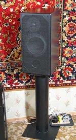
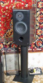
The cabinets are in fact sectioned off below the 8545. It looks to me as though the cabinets are the flat-pack wilmslow vogue cabinets with an additional section below the drivers to create a smaller cab. The build quality looks fine, i.e. nice tight joints, well sealed, foam lined etc.
My guess is that the internal volume of the cabinets is close to that of the Isis standmounts (~19 litres).
Al
Hello, gentlemen.
Happy New Year and Merry Orthodox Christmas to you.
It’s wonder how I missed this thread when I not so long ago searched for information concerning the design of a speaker with this combination of drivers.
I am for the 3rd week having fun with tuning the crossovers for my 8545-9500 bookshelf speakers. I have made some SPL and impedance measurements of both drivers in finished cabinets (in fact I have 6 ea. of 8545 and 4 ea. of 9500 on hands), though, unfortunately I am using some not calibrated Panasonic mike and a preamp, and can only guess what their real curve is. Anyway, my SPL measurements give me the possibility to exactly match the phase and SPL of the drivers in the crossover region. The tonal balance I adjust by the shape of the filter transfer curves in LSPCad and by ears, which I find the most difficult part. The impedance curves in a cabinet, measured by myself with the Speaker Workshop, are correct.
So, if somebody finds this data useful, I will gladly share. At least you will see that the SS 9500 has a much worse SPL problem, than a little hump of the 8545.
Also I already have the release candidate filter schematic and would be glad to share it with Mr. Waltona . It has about 5 dB baffle step compensation and is based on the filter schematic of the M1 speaker http://speakerbuilding.com/content/1021/ with some small corrections. The speakers with the prototype filters sitting on top of cabinets are singing as I am typing this message, and they do it well.
Need to say, that the original schematic by Wilmslow, posted here, with my measurements, in which I trust, shows in LSPCad some odd behavior, very far from flat and phase coherent, with low pass filter curve only 1 dB down at 1000 Hz . I don’t think it can sound well and I am very surprised by this.
Greetings,
Misha
Hi Misha
Very good timing! I have in fact just bought the components to build the M1 crossover and was going to start construction this weekend when I got hold of an inductance meter. I'd be very, very grateful for any information you can give me on your project, in particular:
Your new amended M1 filter
Details of your cabinets (did you keep to a sealed design or do you go vented?)
Did using the 9500 rather than the 9300 involve any changes to the crossover
and most importantly...
How do they sound!
Looking forward to your response.
Cheers,
Al
Hi, Al
Glad that I can help you.
Answering your questions:
I am amazed by the bass capability of these speakers. The bass is very rich and deep. My cabinets are bass-reflex with about 20 liters volume, not counting drivers, bracing and crossovers. Made of 3/4 in birch plywood with 2 levels of internal bracing. All internal surfaces except the front baffle are padded with linoleum, contact-cemented to plywood for damping wall vibrations, and ship fur from my daughter’s old fur coat stapled to the walls to reduce sound reflections. All this made the cabinets very “dead”, and it is vital for good sound, as we know.
The Front baffle is made of 3/4 in plywood with the holes for drivers’ baskets, and glued to it 6 mm plywood with the holes for drivers’ flanges. This way you don’t have to use a router. All drivers are mounted on 2 mm thick rubber gaskets (cut from the wheel tubes – could not find anything better).
The port is made of a standard sewage 2 in PVC pipe with the 52 mm internal diameter. Total length of the port including the thickness of the front baffle is 185 mm.
I made the box modeling in LSPCad and this configuration gave me approx. 37 Hz tuning frequency, which gives good extended bass response with the pretty low group delay.
Having such design, you can revert to the M1’s closed box design by simply plugging the port, if you wish, though I doubt it.
I have made the AutoCAD drawings for all parts, assy, and the 3D model of the speakers. If you have AutoCAD, I can give you the files. Maybe you will find the design a bit too complex, but it is worth it.
When starting making these speakers, I was intended to use them with the support of my Peerless XLS-12/PR sub, but they don’t need it at all. Must say that my room is only 12 sq.m. which I suppose is a lot smaller than yours.
The quality of mids and treble very much depends on the crossover schematic and you can adjust them according to your preferences. Unfortunately, as I told before, I don’t have a calibrated mike nor a big room to make the speaker’s SPL flat just using my measurements. My LSPCad simulations of the M1 and listening to the 1st prototype crossover showed that the M1 has slightly (about 2 dB) recessed to my taste treble level, and the full 6 dB baffle step compensation, which provides a little too much bass in my room. In my design I moved the c/o frequency up a bit (from 1.8 to 2.1 kHz – don’t like the idea to stress a tweeter too much, and also the awful SPL hump the 9500 has goes down better at this c/o frequency), reduced BSC, slightly adjusted the slopes of filters to make drivers’ phase match exactly and tried to find the right tonal balance.
OK, pretty long and enough for now.
If you want me to post some pics, tell me what you need, I will be glad to do it, but some later, at least I need to get home for that.
Regards,
Misha
Hi Misha
Great reply! Great news about the bass response. This is the area where my speakers are currenlty very weak.
I actually already have cabinets that I intend to use. The internal volume is ~15 litres, the walls are lined with 2mm bitumen and 10mm foam. Walls and baffle are all 18mm mdf (a bit think i know).
My plan was to simply switch the crossover, add some extra damping and retune the port.
I'd be very interested to hear about your crossover modifications and what your final crossover design is. I'm guessing that in my room setup 6db baffle step correction could be too much. Any details would be greatly appreciated.
And...photos are always good. Your cabinets sound pretty solid.
Al
And the crossover schematic that I finally came to.
Some comments on the schematics:
In the Net 1 the branch R1011-L1011-C1011 is only for removing the impedance peak, which without it reaches almost 30 Ohm. I don’t think you need to keep it if you have a solid-state amp. R1021 etc is the DC resistance of a coil. R2041=10000 Ohm means no resistor there. If you find the crossover too bright for you, you can make it 50-100 Ohm to slightly lower the tweeter response.
Wish you success with your speakers
Misha
Attachments
Hi Misha
Thanks for the pics and the crossover schematic. Your speakers look great.
Just a quick question about your crossover. Does the LCR section of Net1 make much/any difference to the sound of your speakers? I'll be driving my speakers with a gainclone and I'm not sure how it will cope with that large impedance peak. At the moment I don't have the parts for the LCR network so I'm going to give it a go without. I think I'll start witht the M1 network and ten try your version to see which I prefer. I imagine I'll probably end up somewhere between the two designs.
Thanks again for all you help and tips. I'm really glad you found this thread.
I'll post back when I've got something to report!
Al
Misha
Regarding the impedance conjugate, I might add that it is even more useful with typical solid state amps due to their usually high feedback. Such topologies tend to create correction errors, leading to harsher tone, as they feed the front long tailed pairs with upset information due to highish speaker back emf on their sensing output node.
To the contrary, zero or very low feedback tube amps feel more comfordable with impedance humps in the mids. These are my practical findings and just my 2 cents. In short I would keep the conjugate anyway.
Poka, Salas.
Thank you, Salas
You,ve answered the question that bugged me too, which I also wanted to ask. My speakers are working now with a Pioneer AX3 receiver, which has a power amp with MOSFET output, and I was intended to leave it. As I want to get maximum from my speakers, I will have to find room on my tight crossover boards to squeeze additional components on them.
As an illustration I attached the speaker’s impedance curve without the correction network and with it.
Greetings,
Misha
Attachments
Good. It will sound more open and mellow consistently when using the imp correction, especially in your case that there is sharp Q peak trend without the conjugate.
I have found also that if I dont go for the flatest possible result and I tune the conjugate for a more relaxed effect, I never get some 'deadness' in the mid transients. So for a 100% positive conjugate soundwise, aim for something like this:
I have found also that if I dont go for the flatest possible result and I tune the conjugate for a more relaxed effect, I never get some 'deadness' in the mid transients. So for a 100% positive conjugate soundwise, aim for something like this:
Attachments
Thank you one more time, Salas. One more question for you: what are the power requirements for the elements of this conjugate network? What minimal wire diameter of the inductors and wattage of resistors do you think is appropriate?
As I said, my c/o boards are very small. I guess that this series notch filter consumes current in a narrow frequency range, and also I think the quality of elements should not have impact on sound, if the output impedance of the amplifier is low, which I suppose is the case with my AX3 receiver.
Regards,
Misha
- Status
- Not open for further replies.
- Home
- Loudspeakers
- Multi-Way
- Why don't my Wilmslows sing?