I'm running Class AB.
I did check the 10kHz squarewave at 6.5 Watts output which is about 75% of maximum power. Damping looked close to critical - that is no undershoot, very slight single half cycle of overshoot, edge speeds show evidence of slewrate limiting somewhere in the amp - most likely in the OT itself. I based this opinion on the fact that I could see the edge speed change part way up the slope as the amp transitions from Class A to Class B and the effective drive impedance changes.
I did originally try 1K + 2n2 for the zobels and there was evidence of over damping - serious undershoot which lead me to believe the zobels are in AC parallel. This also "closed down" the sound of the amp both in terms of apparent speed (attack) and in terms of the stereo image. This also stacks up with another theory of mine which is that a lot of the stereo imaging information is in the phase response which is why lots of global NFB kills image stone dead.
I've got to admit that I'm trying to fit theory to what I discovered empirically here.
Cheers,
Ian
The only reason I don't like ultralinear is that once the OPT is wound, the die is cast. You take what they gave you. OTOH, parallel local feedback does the exact same thing, but it's tweakable so that it's NBD to determine what amount of local feedback works best. Don't like the initial results? Simply change one resistor and wash, rinse, repeat.
Parallel local feedback also works best with VTs where G2 requirements are significantly lower than the Vpk requirement (807s, 6L6s, most TV horizontal deflection PAs).
Other than that, it's just two different ways to accomplish the same thing.
Parallel local feedback also works best with VTs where G2 requirements are significantly lower than the Vpk requirement (807s, 6L6s, most TV horizontal deflection PAs).
Other than that, it's just two different ways to accomplish the same thing.
Miles,
What do you mean by parallel local feedback.
In the 6V6 Ultralinear I've just finished I use Ultralinear connection plus balanced shunt feedback from the output tube anodes back to the diffamp front end (Baby Huey scheme with source follower MOSFETs in between diffamp outputs and output tube inputs).
Very similar to this one I posted yonks ago (post #58) except higher shunt feedback (27K in lieu of 13K shunt feedback set resistor) and some additional supplies so I could use my favourite little E-Line Mosfet - a 600mW Zetex ZVN0545A
http://www.diyaudio.com/forums/showthread.php?s=&threadid=72536&perpage=10&highlight=&pagenumber=6
Cheers,
Ian
Miles Prower said:The only reason I don't like ultralinear is that once the OPT is wound, the die is cast. You take what they gave you.
Not sure what you mean by 'the die is cast'. It is like that with*ANY* output. It is up to you to make it as useful as possible when designing it. Like using at least two sets of taps so the U-L ratio can be varied. Getting a secondary with a CT so a little bit ov CFB can be intorduced.
I'd say that the least useful would not even have U-L taps, and secondary taps. One primary, and one secondary...though a fine amp could be built with it and a few pentodes.
cheers,
Douglas
Mmmmh ?
I'm firmly convinced than taps in an OPT are diabolic
You can't have the same leakage inductance for all taps so, whatever you do, you are playing with more than one parameter.
This has to do with the interleaving scheme which is usually unknow, but LL is measurable any way.
Also consider than, the higher the screen tap are, the higher the screens swing and thus produce higher "Miller" effect.
And so, we become more dependant of the driver internal impedance.
I just mean that what is observed in a specific rig may not be reproduced in another one even with same output tubes.
Yves.

Yes okay,....but that's the art in mastering it. It wasn't designed without a bonus. If you want power and negative feedback within the o/p stage then somewhere has to give ground for gain and performance. Part of the problem is that no two manufacturers come up with identical o/p trannies. All have their little quirks. One is for certain, the bigger the beast je more problems one comes up with.
richj
richj
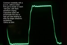
Below is a common waveform problem of many typ UL o/p stages, poor square wave slewing caused by high interwinding capacitances. In this case, a high power 150W wide b/w has large core (10kg) so gets a large area copper exposure. Leakage inductance isn't a problem and maker claims self resonance around 60Khz. The problem gets worse with high drive at high frequencies and leads to waveform ripple. The cure is a Zobel across whole primary, but other parts with compensation i.e front end phase and cap fitted in global nfb line can also effect.
Attachments
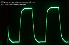
the 2nd photo is after correction.
Not every UL amp will require correction but in this case as the transformer has a 14 section design only a light Zobel compenation was required 500pF and 3K resistor. At full sine or square wave drive (rare in music) considerable power is dissipated and components rated accordingly. I used polypropl cap and metal film resistors.
G2 to anode snubber deficiency wil cause ringing on each waveform half.
richj
Attachments

gingertube said:Miles,
What do you mean by parallel local feedback.
See attached.
Not sure what you mean by 'the die is cast'.
You can't change it once the OPT is wound short of ripping out the primary and rewinding it.
It is like that with*ANY* output. It is up to you to make it as useful as possible when designing it. Like using at least two sets of taps so the U-L ratio can be varied. Getting a secondary with a CT so a little bit ov CFB can be intorduced.
Nice in theory, and wonderful when everything works just like you anticipated it would. Doesn't always happen, and electronic design is as much art as science. Do it long enough, and sure enough, some unanticipated gremlins will rear their ugly heads. In those cases, it pays to be able to improvise.
Attachments
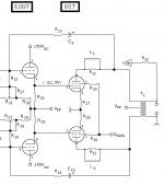
A parallel feedback as shown is nice in theory (it is applied exactly to the same point where input is), and it is indeed very good for the output stage, but what about requirement for much lower resistance to drive it?
It's not a problem since I take care of it by applying the same "Rule of Five" that I use with solid state designs.
It also looks like there's some nonlinearity at the zero crossings. Were they driving it into deep Class AB2? Or is that just a cheap OPT?
Miles # That particular distorted UL waveform was within 2dB from rated power headroom in an output stage behaving goodenough class A i.e Iq 95mA quies was 105mA at 20W o/p(mere 10mA increase). Thd at 20W 1Khz was 0.03% very good.. but at 10Khz = 1%(!!) and there was the problem. Increasing primary current to 110mA per tube reduced thd to 0.5% is a cheap solution but wasteful.
The problem was an o/p tranny with high leakage capacitance, i.e somewhat oversized for the amplifier design. The result is an extended LF response bonus to single figures, I measured thd at 20Hz at around 0.3% confirming high prim inductance combined with an overkill of iron -> to reduce copper area which still cripples the HF response. So there is an equilibrium where oversize can ruin other parameters.
what I'm implying is there's no point using an expensive 18 sectioned o/p tranny where low power is used. Case of going over the books to see the tradeoff between core area, leakage inductance and capacitive losses. No easy task and law of diminishing returns prevails. So there are unskilled manufacturers still around.
I personally like to use o/p tranny size in a circuit where LF cutoff -3dB is around 20Hz giving 1% thd which is around the old industry standard and most designers work to this.
> The result of Zobel trimming is the Penalty for stability by reducing the upper b/w to -3dB at 30Khz not really acceptable for digital reprod but the circuit now accepts the electrostatic loudspeaker whereas before it didn't.
richj
"Optimised?"
Using a 43% lower DC screen voltage will just get you less power output like the triode case. (or a lot of distortion if power is not reduced)
My working hypothesis (working on data measurements to verify this yet) is that the "magic" 43% tap is just the point where screen grid current distortion (using B+ DC on the screens) = the 3/2 power law plate current distortion component, due to a low load impedance. Since they are out of phase they cancel largely. The 43% figure is specific to tube construction (mainly screen grid spacing or equiv. triode configured Mu), so will vary with tube. Nothing magic about 43%.
The effect of the screen current distortion is to syphon off plate current when plate voltage is lower than the screen V. (it is put back into the xfmr primary at a less effective tap) This effectively rounds off the usuall pentode knees in the curves on the left side. A load line then has near equal spacing of plate curves crossing it, effectively eliminating the usual 3/2 power inflation of the curves at high current.
Using a tertiary winding to reduce the DC screen voltage will eliminate the large screen current distortion component leaving one with an un-cancelled large 3/2 power plate distortion at the same power. So power output has to be reduced (back to triode level) to eliminate this high plate distortion.
Screen current distortion is a voltage output dependant factor (and a DC screen V factor). Plate current 3/2 power law distortion is a current output dependant factor (and load Z factor). When a real speaker is connected, inductive reactance will cause voltage and current to go out of phase, and the two distortion components will no longer cancel. So UL tests great on the test bench with a dummy load, but falls flat with most real speakers.
UL was just a marketing trick. There is however some hope that it can be fixed.
Don
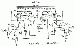
How to Fix UltraLinear:
Active Ultralinear design attached:
Half of the CCS current, times RL, determines the V DC drop on the screens from the plates for the main tubes V1 and V2. Can play with the connection of RL to the xfmr UL tap, instead of to the plate tap, to get correct bootstrap voltage across it. It will then act as an effective CCS load for V3 or V4 and give very high gain to the correction loop from V3 and V4 LTP. Ratio of R2 to R1 sets expected gain or Mu for the output tubes. When the output tubes are operating correctly at this Mu gain, the grids of V3 and V4 are stationary. Any deviation from this Mu rule upsets the V3 and V4 grids and gets corrected by LTP V3 & V4 varying the main tube screen voltages thru the Mosfet buffers.
Don
Attachments
Hi Richwalters,
Is that waveform on your post #73 really that bad?
Examination (as well as I am able to from the drawing) shows a mainly 260 Khz damped ringing. The "serrated" cross-overs indicate the same ringing still, plus an over-compensation by some phase correction cap, probably the lead one over a feedback resistor. (It is not cross-over distortion although it looks similar.) Decreasing this or whatever other move is necessary, will probably show up the full 260 KHz damped ringing with little else wrong. If such ringing is bothersome it can probably be better cured in a somewhat different way.
The "bother" factor is also dependant on a stimulus being there to excite it; in this case the fast rise time of the signal generator. Would such stimuli occur in real life? If so, where is the supersonic filter that should keep it out? The presence of signals there can lead to other problems - no amplifier can be bother-free into the MHz region, any proper design is going to go reactive somewhere. And why should it be bother-free there - cut the frequencies that will stimulate that and forget about it. The same thing, even more so, is relevant to semiconductor circuits. Looking after what happens outside the amplifier pass-band is quite as important in good amplifier design as what is audible.
As you intimate, the rest of the design might well be questionable; I am commenting only with regard to output stages and ringing generated there (which it usually is).
Lastly, I have found in output transformer design a tendency to over-accentuate leakage inductance at the expense of interwinding capacitance. Many products happily go to 100s of KHz because of low leakage, but starts cutting not far above 20 Khz due to interwinding capacitance, especially with pentode circuits. It heavily depends on the design, naturally, but from practical product experience over a wide range of designs, I start running into primarily capacitive attenuation with more than 4 secondaries or so, especially on larger transformers (and I use C-cores which necessitate fewer windings).
Regards.
smoking-amp said:Using a 43% lower DC screen voltage will just get you less power output like the triode case. (or a lot of distortion if power is not reduced)
UL was just a marketing trick. There is however some hope that it can be fixed.
Hi Don,
How to reply to this (again) ......
I am on record stating that I respect your analyses and heaps of work done on this subject, and I am looking forward to results of your particular topology. It will be useful.
But with respect, we seem to be going in circles about certain matters. I have been away from this thread for some time, and there still seems to be something on your mind that (dc) screen voltage must be lower than anode voltage to begin with, and that UL as is, is somewhat of a deception.
I am not also going to repeat, and will just suggest that such a stance does really simply not correspond with practice. There has been so many proper measurements over decades (let us forget about the few poor ones), indicating that UL operation gives most of the good characteristics of pentode and triode stages. I can again only refer to the first graph somewhat down in the reference given in post #76 (for KT88 operation). I have used and measured (on proper instrumentation - I hope you accept an HP spectrum analyser as good enough) similar results in countless cases. Without intending to offend, I must respectfully object to your sweeping simplification that UL "was just a marketing trick". Sorry, friend!
Abundant data and measurements indicate otherwise! Not my fancy; I am just the messenger.
Sure there are less successful designs, etc. etc. - they are not a criterion. And that it can be improved; I would be the first one to laud and adopt any such circuit that anyone can come up with. But for now I get the low distortion (almost triode but at almost pentode outputs and efficiency) shown in manufacturer's data sheets, and I honestly cannot see why I would need much else.
Generally, for the most, screen taps around 40% appear to give lowest distortion/watt output. Lower for 6V6s, but I have not used them much. In my output circuit based on the Quad II topology I need to stay at about 20 - 25% equivalent taps otherwise at the extra amplitude required by the drivers, their distortion begins to become dominent. (I use 6L6s.)
Just some comment on the often maligned taps: As someone said there is leakage reactance - but the effect of that is small compared to primary/secondary leakage because of the different turns ratio. That is part of transformer design anyway, also as said (Richwalters?) - I have never found that a problem. Not to present my results as laudible (I only know them best); is it not satisfactory that a 100W output stage (4 x 6L6GC) with quite a substantial output transformer can give a -3 dB point of 90 KHz after a slight peak and then roll off smoothly (output stage only) at 110W? Etc. etc. for reactive loads, not to bore members.
Lastly, the equivalency of local resistive NFB round a simple pentode stage; it could give similar results, yes. But such designs mostly include the driver stage, and it has been indicated before in an analysis by Prof Matti Otala, that there can be transient distortion problems in an output stage with inherently high internal impedance, reduced to acceptable values by external NFB. Some will argue that UL is also NFB; sure, but it is an inherent output circuit thing, compared to external voltage NFB including a previous stage.
Regards.
- Status
- Not open for further replies.
- Home
- Amplifiers
- Tubes / Valves
- Why do some people dislike ultralinear?