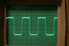
Strapping pentodes as triodes is one of my favourites. Despite mixed commentaries regarding UL, I've found tampering with the R/C screen snubbers makes a large difference in sound quality. Skill is required as g2 snubbers is part of the NFB network and can effect overshoot originating elsewhere in circuitry. I.M.O the 10Khz square wave test at half power into a dummy load is ** tough and highly revealing and all the triode amps I've sampled can't create decent waveform without massive slewing.
The AB2 amp I botched up from clear 6550B's is indictative how excellent the UL class is. Beat this waveform ??
The AB2 amp I botched up from clear 6550B's is indictative how excellent the UL class is. Beat this waveform ??
Attachments
Wavebourn said:Do you mean 15% of voltage, or impedance ratio?
That would be voltage ratio.
Douglas
richwalters said:Strapping pentodes as triodes is one of my favourites. Despite mixed commentaries regarding UL, I've found tampering with the R/C screen snubbers makes a large difference in sound quality. Skill is required as g2 snubbers is part of the NFB network and can effect overshoot originating elsewhere in circuitry. I.M.O the 10Khz square wave test at half power into a dummy load is ** tough and highly revealing and all the triode amps I've sampled can't create decent waveform without massive slewing.
The AB2 amp I botched up from clear 6550B's is indictative how excellent the UL class is. Beat this waveform ??
Unbelievable!!!
Can you draw your trick with resistors/capacitors?
Most clever that I managed to invent was putting bright red LEDs in screen grids to indicate saturation. Electro-human feedback" Hey dude, pull down faders!"

An old trick to get cathode feedback is to put the secondary in the cathode circuit. You won't get a lot of feedback; connecting the cathode to the 8 ohm tap on a 5k SE transformer only puts 4% of the windings in the cathode circuit, but it's worth trying if you want to experiment.
It can be done with a PP transformer if there are 4 and 16 ohm taps. Ground the 4 ohm tap and connect the cathodes to the 16 and 0 ohm taps. Trouble is, the secondary of most PP OT's of that kind (vintage consumer grade stuff) is not going to be very well balanced either side of the 4 ohm tap, so results might be marginal.
-- Dave
Wavebourne# As you know going into AB2 with a conventional p-p UL setup carries a severe overcurrent penalty, in my case Iq = 60mA and full load (which is somewhat unreal) can hedge 200mA per tube and drastically limit tube life. (Although is tempting Don't do cont sine wave on this!) My safe hedge is to limit B+ in my amp to 350V and this provides roughly 35W from a pair of glass button gettered 6550B's. (Be honest ...I would have never expect such craving performance from such boring plain looking tubes). ??
The trick... since I use ECL82 pents (as triodes) Lowish'' Z phasesplitter drivers and used the surplus ECL82 triodes signal section as diodes which behave soft. The caveat is to run the o/p tubes with an over impedanced primary 4.5KA_A. (43% taps). For the 6550 stats this would appear to break the rule books regarding power throughput and forcing a 5Khz sinewave through the block gave an overload waveform too ugly i.e it was creating foldback rectification voltage limiting by upsetting the real DC component of g1. SO I did the old AB2 guitar amp trick of strapping the ""tube diode"" from g1 to fixed bias neg via resistor. (cathode to signal) This forces the o/p tubes to respond and care must chosen with series resistor value to actual power throughput.
The initial problem was high THD at 10Khz. The output stage impedance reflection match was wrong ( I knew it was) so I tried AB2 forcing and it worked and reduced thd by more than half. A masssive improvement. It can only work if the power supply can hold up such enormous signal transients and not voltage droop. Bear-in-mind AB2 condition is really intermittant i.e music and speech, and doing sine wave tests can also Jarr up the output tranny ! Fit a fuse !!
To the crux.The g2- anode snubber R/C value is critical for optimal waveform squarewave ripple BUT the Global NFB (my case 20dB)also throws the towel in as well as the phase compensation in the first stage in a 4 stage amp. This is the surprise jewel....A good amp design of nom 20dB global NFB should be able to take an extra 15dB NFB before instability sets in. I found improved transient reproduction with correct g2 to anode RC components, in my case with a good quality o/p tranny with low leakage L , I arrived at the values of 1K5 and 330pF (silvered mica). This was a vast improvement to the recommended 1nF/1K which created considerable overshoot. The low freq end, using a 100W p-p o/p tranny on 35W should enable a single frequency figure power throughput. In my case 7Hz. This is too low so I reduced phasesplitter coupling cap values to create 1% thd at 10Hz. This created enough loop gain (15dB) at 25Hz to effectively dampen the LS. Got the Jist ?? With single shot LF square wave YOu might find the amplifer transient response also coincides with optimum Q. Yes.
More anon
richj.
Rich,
Yes those zobel networks from screen to anode are "required". They make a huge difference to the Ultralinear Sound. I routinely put them into every Ultralinear Amp I build and so it was one of those things I forgot to mention because I do it without thinking about it. Another local constructor reported a huge improvement as well when he followed my suggestion to him to put them in.
On one amp using 4 x KT88 in Parallel Push Pull Ultralinear into a Hammond 1650T tranny I actually borrowed some gear from work and did full magnitude and phase plots (Bode Plots) before and after fitting the zobels and it was quite clear that it was effectively suppressing transformer resonances. I used voltseconds methods to optimise the zobels. Here is the link
http://www.siteswithstyle.com/VoltSecond/Damping_ringing_XFMRS/Damping_ringing_in_xfmrs.html
Interestingly I ended up with different zobels on the push and pull sides and that is something that I've never seen before. I used teh Rd_opt_Zi values.
Method (in brief) was to build the output tubes stage (i.e no phase splitter/driver) and drive one side at a time from the signal generator while looking at the anode signal on the CRO, with the otherside at DC idle. Then identified the side with the lowest resonance frequency and tackled that first.
A big clue as to why zobels might be required was given in my experience with the Menno Vandervenne VDV70/100 amps I built some years ago. (Parallel Push Pull EL34 into a Toroidal Output Tranny with badwidth to >200kHz). The amps had 150R series screen resistors. It worked fine in triode mode or pentode mode but suffered "squegging" (bursts of high frequency oscillation) when in ultralinear mode. In that case I did'nt get around to fitting zobels but I did confirm that increasing the screen series resistor from 150R to 1K cured the problem. Menno since posted this "fix" on his web pages.
Cheers,
Ian
In a well balanced/ made o/p p-p tranny the Zobel should be identical each side. One little trick I often do is to run a 5Khz square wave at low power through the amp into a dummy and substitute the global nfb resistor with a pot and see how much extra nfb the amp can accept before instability sets in. This is a pretty good test and at the same time one can tweak front end zobel and other values. Oscill'Probe earthing is also important.
Bear in mind (big admission) with big amps it can be frustrating switching on and off and waiting for warm up adjusting components but I always fit a hot switch which can turn the B+ off. I've been in the tube business for some time and acquired the (bad) habit fiddling with circuits while B+ is up......and poking with an unearthed soldering iron..(who hasn't done this ????).
richj
Wavebourn said:
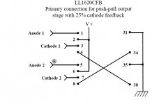
What ratio is optimal for cathode windings?
LUNDAHL uses 25% in its LL1620CFB model.
In reading others experiences and methods, it strikes me how much effort is required to get UL working right! Maybe straight pentode or triode mode is actually easier and less sensitive to circuit variations!??
Having designed and built multiple examples of all three (and a few more) I don't think so. Each one has its own set of issues that has to be dealt with. Triodes have reactive inputs and need regulated plate supplies (or can only be run class A), pentodes need tightly regulated screens and tend to be very load sensitive, UL needs tight coupling in the transformer and better plate regulation than pentode. Circlotron needs lots of drive and two floating power supplies per channel. Unity coupled needs a transformer with tight multifilar winding. And so on and so on.
SY, it still seems to me that UL has its unique features. Only in UL does the screen current go through some part of the primary winding; it doesn't with either pentode or triode. It follows that the OPT should therefore be more of a factor in the quality and stability of a UL amp than either of the other two.
Of course, a good quality OPT is still important with any of these topologies, but I can't help thinking that triode offers the simplest solution. You need to add little or no NFB with triodes (depending on the needs of your speaker), so instability at the extremes of the frequency spectrum is unlikely to pose a problem.
Of course, a good quality OPT is still important with any of these topologies, but I can't help thinking that triode offers the simplest solution. You need to add little or no NFB with triodes (depending on the needs of your speaker), so instability at the extremes of the frequency spectrum is unlikely to pose a problem.
SY, it still seems to me that UL has its unique features.
Yes it does. That was exactly my point. So do triode and pentode, just different ones in each case. Triodes have input capacitance issues and (to operate properly) need tightly regulated plate supplies. Those are not trivial considerations.
Hey Sy,
You keep saying that triode amps need tightly regulated plate supplies. How tightly regulated? Perhaps it is just our definitions of 'trivial considerations' differ. An LC filter for a Class A PP amp is just a minimum starting point. If it needs to be really stiff, try Hg vapour diodes...🙂
It seems that the triode is the least concerned with its exact operating point. Shift it around a little bit and nothing big hapens. OTOH, move a pentode amp's plate supply a bit and all on a sudden you're driving the load line out through the knee and odd HD starts happening in big way.
Anyway, I just rigged the output stage of my latest amp 40% U-L. I have the choice of 20 and 30%( though also the trouble of dealing with the unused taps ). 30% taps feed the E-Linear driver/FB stage. The OPT is a decent one that I've used previously. It's winding geometry is from the Peerless S-265. 10 layers on each side of the CT leaves convenient end-of-layer tap points.
cheers,
Douglas
One of the big reasons that mediocre triode amps can sound mushy and indistinct is the rails moving around with signal, especially if you run the amp sensibly in AB (which will challenge the Hg/LC passive approach). It will still work after a fashion, but will be suboptimal- analogous to UL with a less-than-stellar transformer.
The single biggest improvement to the triode amps I've built was putting in low impedance active regulation on the plates. That did more to unmush and tighten the sound than any other tweak I've tried, but is complex if it is designed to actually survive the rigors of real-world use.
The single biggest improvement to the triode amps I've built was putting in low impedance active regulation on the plates. That did more to unmush and tighten the sound than any other tweak I've tried, but is complex if it is designed to actually survive the rigors of real-world use.
Getting those Zobels about right
Mucked about with the zobels on the 6V6 Ultralinear over the last couple of days.
Transformer is 8K : 4 Ohms
Np/Ns = 44.72
For Anode to Screen one side
44.72 / 2 * 0.57 = 12.75
So for my nominally 6 Ohm speaker on the 4 Ohm secondary tap we reflect 974.6 Ohms between anode and screen taps.
So choose 1K for the Zobel resistor.
With zero feedback do a frequency response sweep - noted that the first transformer resonance creates a peak at 74kHz.
for R = 1K and F = 74kHz then C = 2.15nF
BUT we are adding 2 of these things - one each side and they will be effectively in AC parallel so actually want 2 off 148kHz networks so that in parallel they give 74kHz.
So I fitted 1K + 1nF zobels between anode and screen each side. A quick check of the no feedback, full power frequency response shows that the resonance peak is gone and -3dB point which was 36kHz is now about 34kHz.
Put the feedback back in and sit down for a listen.
Much more detailed and refined, smooth, easy top end. A big improvement.
Cheers,
Ian
Interesting - I'm building an SE ultralinear amp using 1625 outputs. Has anyone tried plate to screen zobel networks in an SE amp?
Ultimate check for zobel and general compensation is to slam a square wave between 5-10Khz though the amp about 2/3 power out into a dummy load and look at the quality of it.
Hey Ginger!,
Does the class of operation have anything to do with your calculations? and is your output tap percentage exactly 43%? Seems like for an amp running Class A, you'd want 43% of 4k.
cheers,
Douglas
Does the class of operation have anything to do with your calculations? and is your output tap percentage exactly 43%? Seems like for an amp running Class A, you'd want 43% of 4k.
cheers,
Douglas
- Status
- Not open for further replies.
- Home
- Amplifiers
- Tubes / Valves
- Why do some people dislike ultralinear?