Thanks for this trobbins. I vaguely remember the article. Brings back memoriesthe Radford MA15 Mk2 amplifier design was described in detail in HiFi News 1962 in 4 parts by Bailey and Radford. Design is based on the Mullard 20W amp from 1955
Going back to the OP, he quotes Morgan Jones criticising 5-20 for 'only' having a bandwidth of 100kHz as though that was important. MJ has loadsa good stuff but also a lot of liquid BS.
His remarks about overload implies da old gurus never tested for overload but the HFN article shows exemplary overload performance (in 1962) .. MUCH better than many modern Golden Pinnae amps.
These are STILL employed in modern amps, both valve & solid state. They are an important tool if you are concerned with unconditional stability with load.The MA15 also added LF and HF step networks to manage its feedback level back to 20dB
In some 2 decades of DBLTs, overload performance & stability are the 2 features that determine audible difference & preference in amps. Many (all?) Golden Pinnae amps are unstable on real speaker loads .. all subject to programme & thermal history. No wonder they sound different.
BTW, 5-10 is noisy cos its high sensitivity. But 5-20 is not noisier compared with modern amps.
I built two versions of Crowhurst's Twin Coupled Amp. It is a way to get a poor man's version of a McIntosh.if Norman Crowhurst were here today, he'd be very elated....
Both built in the past 25 yrs for experimental & measurement experiments. The first is a PP output of 6LU8s.
The triode in each forms a CF driver for the pentode. The amp has a SS regulated B+ with some delay built in. 400V B+ on the plates.
300V on the screens, the drivers & CFs are bootstrapped just as in the McIntosh. The OPTs are simply a pair of Hammond 125E's.
The front end is a 2-stage diff-amp, 6SL7 & 6SN7, simple resistive tails to -150, regulated. Switchable to Crowhurst's front end.
The wooden end pieces are not there for beauty but rather a convenient stand as changes & measurements are taken.
About 35 watts at clipping. And very good test results, Harmonic Distortion, IMD & so on. Better than most would expect.
I've never built a Mullard, Williamson. Dyna or any of the other common amps. They have all been done & over analyzed, there is
little left to the imagination! 😀
Attachments

absolutely.....
Uh-huh. And yet...for naturalness of tone and solidity of imaging, a properly stabilized Williamson beats a Mullard circuit hands down to my ears. I'd be happy to do a shoot-out any time. ;-)
Given the Williamson (and other) amps can have an uncertain HF stability, especially with alternative output transformers (including modern day alternatives), I'm about to start some gain-phase testing out past 96kHz on the few OPT's I have. Interestingly, Williamson was able to do a gain-phase from 1Hz to 1MHz to show margins at each end back in mid 1940's, but I've not encountered anyone else doing that in public up until that 1962 paper by Bailey & Radford, and since then very few have made much effort - rather relying on squarewave testing and load variation to confirm stability.I've never built a Mullard, Williamson. Dyna or any of the other common amps. They have all been done & over analyzed, there is
little left to the imagination! 😀
Williamson and Bailey/Radford did gain/phase plots manually, and I have too, but its a pain. Nowadays it's relatively easy to do up to 96kHz, but all the interesting stuff relating to feedback compensation and what transformer resonances are forcing a heavy handed dumbing down of feedback at relatively low frequencies (like what Bailey/Radford had to do), require a different form of modern day instrumentation, so I'll hopefully have a go with a Picoscope and some software to make plots out to 1MHz. That should allow better appreciation of some forms of compensation, including a series inductor in the load ground path that Patrick Turner included in some of his amps, as well as subtleties of secondary winding configuration options, and direct comparisons of OPTs.
The front-end topology of the Mullards is also my favourite and what I like most (sound) with pentode power tubes. I don't use the input pentode because I don't need all that gain as my power amps only have moderate cathode feedback (7 dB with EL34s) and no GRND feedback. Lately I have been using a simple SE stage with the PCC88 where its second triode makes a CCS running at about 5 mA with approx. equivalent 80K tail resistance for the ECC81 LTP. I can really get a lot of undistorted swing with enough voltage supply which is not difficult as the EL34's work from 450V anode voltage.In my fossilized opinion, the Mullard 5-10 & 5-20 are bullet proof circuits when carefully built,
without dry solder joints.
Last edited:
How did you check for stability? Done any overload tests with 'real' loads?Uh-huh. And yet...for naturalness of tone and solidity of imaging, a properly stabilized Williamson beats a Mullard circuit hands down to my ears. I'd be happy to do a shoot-out any time. ;-)
Last edited:
Can you show a schematic?I built two versions of Crowhurst's Twin Coupled Amp. It is a way to get a poor man's version of a McIntosh.
Not sure how you connect a Hammond 125E for a McIntosh / Crowhurst circuit ... which requires separate Anode & Cathode windings for each output tube (4 identical windings) ... while 125E has a single centre-tapped primary and is only rated at 15W 150Hz.
The 'ultimate McIntosh' is of course the QUAD II though arrived at from a very different viewpoint.
Last edited:
i have Norman Crowhurst to thank for my tube education, and of course the tube gurus here and they are many....I built two versions of Crowhurst's Twin Coupled Amp. It is a way to get a poor man's version of a McIntosh.
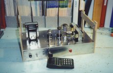
Both built in the past 25 yrs for experimental & measurement experiments. The first is a PP output of 6LU8s.
The triode in each forms a CF driver for the pentode. The amp has a SS regulated B+ with some delay built in. 400V B+ on the plates.
300V on the screens, the drivers & CFs are bootstrapped just as in the McIntosh. The OPTs are simply a pair of Hammond 125E's.
The front end is a 2-stage diff-amp, 6SL7 & 6SN7, simple resistive tails to -150, regulated. Switchable to Crowhurst's front end.
The wooden end pieces are not there for beauty but rather a convenient stand as changes & measurements are taken.
About 35 watts at clipping. And very good test results, Harmonic Distortion, IMD & so on. Better than most would expect.
I've never built a Mullard, Williamson. Dyna or any of the other common amps. They have all been done & over analyzed, there is
little left to the imagination! 😀
i will try theat twin coupled amp one of these days...
How did you check for stability? Done any overload tests with 'real' loads?
My current Williamsons, which use a Heyboer copy of the Peerless S-265-Q, will not break into HF oscillation either unloaded, with .22uF across the load or with a .047 capacitive load only. That's not bad. It could possibly be better but I'm still learning about phase margins and how to identify and improve them. In any event, I don't think they'll eat my ProAcs. ;-)
If you modify a vintage Williamson using Dave Gillespie's instructions over at Audiokarma, you can be assured that the amp is very, very stable and performs as well as that amp possibly can. I recently sent Dave a Heyboer/Peerless S-265-Q for testing and he gave me some tips for getting the best performance from it. He also felt that it was an excellent copy, with only "incrementally less" performance than the original.
He's currently working on an Audiokarma thread about the Heathkit W5 which will include the two Peerless outputs originally designed for that amp as well as information on the original Peerless S-265-Q and the Heyboer copy. Since W5's are still plentiful on the second-hand market I imagine it will be of great interest to DIYers.
You can also always add a zobel network across the output for safety, but it can affect performance and I prefer to do without it if possible.
Last edited:
Can you show a schematic?
Not sure how you connect a Hammond 125E for a McIntosh / Crowhurst circuit ... which requires separate Anode & Cathode windings for each output tube (4 identical windings) ... while 125E has a single centre-tapped primary and is only rated at 15W 150Hz.
The 'ultimate McIntosh' is of course the QUAD II though arrived at from a very different viewpoint.
The Crowhurst Twin-Coupled amp uses two identical output transformers. Not quite the same as McIntosh's "Unity Coupling" but it's similar in purpose.
https://www.pearl-hifi.com/06_Lit_Archive/02_PEARL_Arch/Vol_01/Sec_03/190_Twin-coupled_Amplifier.pdf
Can you show a schematic?
This project was originally published in the Volume 35, Issue 8 of AudioXpress magazine in August of 2004.
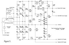
One of the schematics here shows a simplified version of Crowhurst's idea.
The transformer primaries in this case are tied together using a pair of 100 microF electrolytics.
In all of my projects I tried whenever to use off-the-shelf parts so that anyone could do the build at reasonable cost.
This often requires some compromises. The H125E's do not have ratio's suitable for secondary parallel operation.
To get the loadline required it was necessary to use series connexions. The result is DF of about 3.
The attached Amp schematic uses the Crowhurst front end. As built, it is switchable to full differential.
Money would have bought the correct OPT's. But I already had the data I was looking for.
This & several other projects are all experimental. I moved on.😀
While on a business trip to Calgary around 1980 I made a point of connecting with Bill Perkins of PEARL.
PEARL- Perkins Electronic & Acoustics Research Lab.
He was extremely busy with several projects on the go. When I joined HP in 1965 I left behind all the popular electronics magazines.
During our talk I found that Bill P was attempting to put many of the important articles back into some kind of searchable file.
I had wished to have kept a copy of Crowhurst's work on his Twin Coupled Amps. Bill pulled them up & made copies for me. 👍
Attachments


Last edited by a moderator:
it was a low cost solution to the McIntosh..The Crowhurst Twin-Coupled amp uses two identical output transformers. Not quite the same as McIntosh's "Unity Coupling" but it's similar in purpose.
I ask again. Which model was that?The best Radford amp made was not that one but had a ECC81 SRPP at the input DC coupled to the classic ECC83 LTP with EL34 output stage.
Thanks for this grovergardner & jhstewart9. I have a Crowhurst book which mentions his Twin-Coupled amp but the circuit shown led me to think he was describing the McIntosh.The Crowhurst Twin-Coupled amp uses two identical output transformers. Not quite the same as McIntosh's "Unity Coupling" but it's similar in purpose.
https://www.pearl-hifi.com/06_Lit_Archive/02_PEARL_Arch/Vol_01/Sec_03/190_Twin-coupled_Amplifier.pdf
It has the same cons as the McIntosh but is certainly worthy of further study.
Thanks for this Grover. Does this mean you found some instability with other loads? In my previous life, Williamson (in)stability was of great interest to me. 🙂My current Williamsons, which use a Heyboer copy of the Peerless S-265-Q, will not break into HF oscillation either unloaded, with .22uF across the load or with a .047 capacitive load only. That's not bad. It could possibly be better but I'm still learning about phase margins and how to identify and improve them.
If a Zobel 'affected performance' it would certainly have affected the sound. I would have it in. Marginal stability is one of the things proven to make amps 'sound different'. 😱You can also always add a zobel network across the output for safety, but it can affect performance and I prefer to do without it if possible.
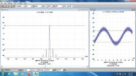
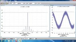
I can't push the capacitance too high, loaded or unloaded, or it will oscillate, but as it is I think it's pretty solid. Dave Gillespie suggested a fairly steep step filter to use with the Heyboer/Peerless and it works pretty well, given that I'm not yet skilled enough to do the kind of fine-grained stabilizing he is able to do. They sound much better than with the stock compensation networks I was using, I can tell you that. Here's a 10kHz square wave at 8 ohms @ 1 watt:

In my experience a zobel can affect the sound, but it can also cure a lot of ills. ;-) I'll have to experiment with one on these amps.
My Picoscope has the ability to pinpoint phase shifts and margins up to 1mHz, but I need to learn what to do with that information. ;-)
In my experience a zobel can affect the sound, but it can also cure a lot of ills. ;-) I'll have to experiment with one on these amps.
My Picoscope has the ability to pinpoint phase shifts and margins up to 1mHz, but I need to learn what to do with that information. ;-)
I'm getting in a 4224A next week, so am setting up one of my Williamson's now, as I used that amp to test a few OPT's last year along with Patrick Turner's compensation technique. https://dalmura.com.au/static/Williamson output transformer measurements.pdf
Zackthedog over on audiokarma really piqued my interest in the picoscope measurement system 4 years ago - it all takes time!
https://audiokarma.org/forums/index...ess-williamson-final-assessment.875351/page-6
Ciao, Tim
Zackthedog over on audiokarma really piqued my interest in the picoscope measurement system 4 years ago - it all takes time!
https://audiokarma.org/forums/index...ess-williamson-final-assessment.875351/page-6
Ciao, Tim
- Home
- Amplifiers
- Tubes / Valves
- Why are people still touting the Mullard 5-20 circuit?