It makes an excellent driver DN2540 can also be used. 3 ma idle current will drive anything tube.
It's not a 5-20 without the pentode front end and 12ax7 splitter. Your implementation is far better.
It's not a 5-20 without the pentode front end and 12ax7 splitter. Your implementation is far better.
It is the year 2023 and I still think that the 5-20 is one of the best capable amplifiers out there that you can easily get parts for and is relatively simple and very powerfull.
I only have 2 main issues with the original. High input gain and the "weedy" driver stage for the EL34s.
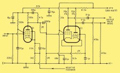
In an effort to solve these problems I have kept the original EF86 designed a biasing circuit arround it in the cathode and made it so it accepts a +4dBu input level with the original EF86 and the driver stage was remodelled with a ECC81 a current source in the cathodes and grid biased EL34s for that extra botom end safety margin (with auto biasing circuit for them too)
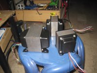
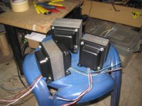
When you use PROPER iron, and by that I mean the polish TTG Toroidy transformers which are toroidal sintered powder core transformers that have a frequency response of 8Hz to 54kHz -3dB this thing beats most transistor amplifiers in sounding basically like a refference amplifier. (extremely sterile with stern bass response). With the incredibelly high NFB its basically only as tube sounding as the EF86 itself is. And with it modified to take a +4dBu signal thats very little.
Stabillity wise I only had issues at the lowest of the low frequencies 5-4Hz due to the transformer being far better than the circuit originally was designed for.
I could let loose the anode RC compensation and this thing would go 10Hz-50kHz literary flat 20W RMS output power.
To adress some misguided opinions here.
The original amplifier was noisy because the anode resistor of the EF86 was likely really done for. With brand new ROHM resistors this thing was dead silent with the original gain setting (grounded input)
The driver is quite sub par. But not bad enough that it would impede performance hugely unless driven into absolute extremes. Adding in very large cappacitors into the cathodes of the final stage helped the low frequency response so it wouldnt get into gain limitations in the driver, however I found that grid biasing wasnt going to be an issue to mod in so I have done away with the cathode biasing and added in my automatic biasing circuit that sets grid voltage to achieve a set cathode current.
Even if I were to let the 12AX7 live in my ampifier I dont think it would have cause much trouble. The thing is that the EL34s are quite easy to drive tubes and they really dont mind being driven from such a high impedance source. Even if it is a little non ideal.
I really like the topology used in the 5-20 and assuming that we can expand on it with todays knowledge and components (Transistor voltage regulators for each stage) we can make it perform more like a powerful amplifier that has no distinctive sounding compared to a refference amplifier. Quite impressive that we can achieve such parameters with devices designed more than half a century ago passing sound, with transistors just assisting the operation.
I only have 2 main issues with the original. High input gain and the "weedy" driver stage for the EL34s.
In an effort to solve these problems I have kept the original EF86 designed a biasing circuit arround it in the cathode and made it so it accepts a +4dBu input level with the original EF86 and the driver stage was remodelled with a ECC81 a current source in the cathodes and grid biased EL34s for that extra botom end safety margin (with auto biasing circuit for them too)
When you use PROPER iron, and by that I mean the polish TTG Toroidy transformers which are toroidal sintered powder core transformers that have a frequency response of 8Hz to 54kHz -3dB this thing beats most transistor amplifiers in sounding basically like a refference amplifier. (extremely sterile with stern bass response). With the incredibelly high NFB its basically only as tube sounding as the EF86 itself is. And with it modified to take a +4dBu signal thats very little.
Stabillity wise I only had issues at the lowest of the low frequencies 5-4Hz due to the transformer being far better than the circuit originally was designed for.
I could let loose the anode RC compensation and this thing would go 10Hz-50kHz literary flat 20W RMS output power.
To adress some misguided opinions here.
The original amplifier was noisy because the anode resistor of the EF86 was likely really done for. With brand new ROHM resistors this thing was dead silent with the original gain setting (grounded input)
The driver is quite sub par. But not bad enough that it would impede performance hugely unless driven into absolute extremes. Adding in very large cappacitors into the cathodes of the final stage helped the low frequency response so it wouldnt get into gain limitations in the driver, however I found that grid biasing wasnt going to be an issue to mod in so I have done away with the cathode biasing and added in my automatic biasing circuit that sets grid voltage to achieve a set cathode current.
Even if I were to let the 12AX7 live in my ampifier I dont think it would have cause much trouble. The thing is that the EL34s are quite easy to drive tubes and they really dont mind being driven from such a high impedance source. Even if it is a little non ideal.
I really like the topology used in the 5-20 and assuming that we can expand on it with todays knowledge and components (Transistor voltage regulators for each stage) we can make it perform more like a powerful amplifier that has no distinctive sounding compared to a refference amplifier. Quite impressive that we can achieve such parameters with devices designed more than half a century ago passing sound, with transistors just assisting the operation.
i have the 6bh11 compactron version as yet another drive board to the Dynakit ST70..https://www.jogis-roehrenbude.de/Roehren-Geschichtliches/Compactron/6BH11/6BH11.pdf

@TonyTecson
I suggest you add transistor voltage regulation at least for the EF86 to prevent low frequency instabillity. It does help behaviour in certain situations. Especially if your power supply is not that greatly filtered. The inverter driver dooesnt care but the EF86 certainly does.
I suggest you add transistor voltage regulation at least for the EF86 to prevent low frequency instabillity. It does help behaviour in certain situations. Especially if your power supply is not that greatly filtered. The inverter driver dooesnt care but the EF86 certainly does.

nah, i'd rather not....if ever, i will use a tube gas regulator 0a2, the ef86 voltage amp stage is very crucial for noise and stability, getting it with a stiff B+ is important, that is why i use dc filaments...@TonyTecson
I suggest you add transistor voltage regulation at least for the EF86 to prevent low frequency instabillity. It does help behaviour in certain situations. Especially if your power supply is not that greatly filtered. The inverter driver dooesnt care but the EF86 certainly does.
Bob Carver's silver 7 used zener diodes to do that...
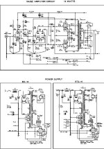
the Radford circuit is a definite improvement over the Mullard 520... https://www.ampslab.com/SCHEMATICS/LowRes/Radford_STA15.jpg
Attachments
Youre complaining about noise yet you like the idea of 7 zeners...let me break it to you they are NOISY.nah, i'd rather not....if ever, i will use a tube gas regulator 0a2, the ef86 voltage amp stage is very crucial for noise and stability, getting it with a stiff B+ is important, that is why i use dc filaments...
Bob Carver's silver 7 used zener diodes to do that...
give me one objective reason why not to use a LR8 with a pass transistor. Just one will be enough.
Gas discharge regulators are getting exceedingly rare these days. Besides you have no idea what voltage is the EF86 supply sitting at until you measure it. And I can tell you it is not a standard voltage for zeners nor gas discharge tubes.
I put the LR8 into just about EVERYTHING. I regulate the anode voltage for the finals the inverter and VAS separately and its a way nicer behaving circuit than before. And no noise issues.
Noise is only a problem if you dont know what youre doing.
I would like to see data on the "better" schematic...because from where I am standing it look like an even bigger tragedy using a cheap TV tube that has no business in audio application.
you mean Bob Carver, the famous designer loves noise? if i can not hear the noise in my speakers why should i complain?Youre complaining about noise yet you like the idea of 7 zeners...let me break it to you they are NOISY.
because it is a solid stage amplifier, in my tube amps i want nothing to do with solid state amplifiers.. you have every right to use it on yours but do not tell me i should use it in mine....give me one objective reason why not to use a LR8 with a pass transistor. Just one will be enough.
not a reason not to try...Gas discharge regulators are getting exceedingly rare these days. Besides you have no idea what voltage is the EF86 supply sitting at until you measure it. And I can tell you it is not a standard voltage for zeners nor gas discharge tubes.
then good for you, but for me, no thanks, hey this is diy and we are allowed to do our thing, but only if it is safe and not endanger another..I put the LR8 into just about EVERYTHING. I regulate the anode voltage for the finals the inverter and VAS separately and its a way nicer behaving circuit than before. And no noise issues.
wow, big words, i will never say these words...Noise is only a problem if you dont know what youre doing.
what data? if only build one to my enjoyment, something wrong with that?I would like to see data on the "better" schematic...because from where I am standing it look like an even bigger tragedy using a cheap TV tube that has no business in audio application.
do not belittle on "cheap TV tube that has no business in audio application." you are of course entitled to your own opinions...the tons of work done by Tubelab.com and smoking-amp and many others about tv tubes is no laughing matter, don't use tv tubes if you think they are not worth it, as easy as that..
https://www.diyaudio.com/community/threads/those-magnificent-television-tubes.211254/page-92
with 92 pages, 871k replies, 11 years running......
Last edited:
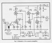
I disagree about that odd phase splitter. The best Radford amp made was not that one but had a ECC81 SRPP at the input DC coupled to the classic ECC83 LTP with EL34 output stage. In my experience, it's better in any way: sound and measurements.a new phase splitter: http://www.r-type.org/articles/art-097.htm
In my fossilized opinion, the Mullard 5-10 & 5-20 are bullet proof circuits when carefully built,
without dry solder joints. If the gain is too high it is easy to rewire the EF86 / Z729 for triode operation.
Then adjust the NFB to suit. If there is a noise problem in the front end, stuff in another EF86.
Or start looking for a noisy resister.
The fossils like me here on DIY had more serious noise challenges to deal with,
The signal from a vinyl player thru a magnetic pickup is usually mVolts.
But many solutions were found.
Attachments
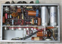
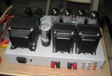
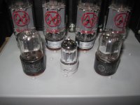
my best implementation of the Mulard520 had the 5814 in front as voltage amp, the 6SL7 in ltp and JJ6L6gc output tubes, my client was very happy and i am happy for him, the amp is now in Australia and making good music...In my fossilized opinion, the Mullard 5-10 & 5-20 are bullet proof circuits when carefully built,
without dry solder joints. If the gain is too high it is easy to rewire the EF86 / Z729 for triode operation.
Then adjust the NFB to suit. If there is a noise problem in the front end, stuff in another EF86.
Or start looking for a noisy resister.
btw, the JJ's were really matched in bias at 22.6x vdc, individual cathode bias resistors, how close can you get?
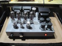
below is the said amp, all irons that i used were all designed and built my me....
Attachments
The Mullard 5-20 is iconic cos its topology is the final iteration of great valve amps.
Can it be improved? Of course! But the last great valve amps, the Radfords, LEAKS, late Dynacos, Harmon Kardon and even Bob Carvers Silver 7 are ALL just (??) 'improved' 5-20s.
I was lucky enough to have long discussions on amp design with Peter Walker, Arthur Bailey, Great Guru Baxandall and was privileged to work closely with Ted Ashley (who designed the last of the great LEAK amps). These illustrious gentlemen, though all retired from amp design, were still as sharp as paint and fully aware of all modern developments.
You'd be surprised at what 'modern components' they wished they had when they were designing amps.
Ted said that though he could argue ad infinitum whether the LEAK version of 5-20 was better than the Radford version, he reckoned the real reason for their good performance was cos Radford wound their own transformers .. and LEAK had a very close relationship with Drake who supplied their transformers.
I would add, they also had Mullard valves hand crafted from solid Unobtainium & BS by virgins in the great Blackburn factory, 🙂
The 5-10 wasn't quite in the same league but the 5-20 today, with its 220mV sensitivity, is almost ideal for driving directly from a CD player via a 10k pot.
There are loadsa simple tweaks that 'improve' a 5-20 but few are likely to result in better sound. One, not so simple, which does result in better sound, is to run it from a customised regulated SMPS .. but this would also improve ALL Class A amps.
The really nasty 'vintage' amp is in fact the Williamson. Hugely expensive, VERY prone to oscillation and outperformed in every way by the far simpler 5-20
you bet....if Norman Crowhurst were here today, he'd be very elated....You'd be surprised at what 'modern components' they wished they had when they were designing amps.
my thoughts too...i have used the smps in NP's ACA amp and will ever go back to tradition psu...There are loadsa simple tweaks that 'improve' a 5-20 but few are likely to result in better sound. One, not so simple, which does result in better sound, is to run it from a customised regulated SMPS .. but this would also improve ALL Class A amps.
this is something that non transformer winders will ever get....Ted said that though he could argue ad infinitum whether the LEAK version of 5-20 was better than the Radford version, he reckoned the real reason for their good performance was cos Radford wound their own transformers .. and LEAK had a very close relationship with Drake who supplied their transformers.
absolutely.....The really nasty 'vintage' amp is in fact the Williamson. Hugely expensive, VERY prone to oscillation and outperformed in every way by the far simpler 5-20
On the topic of Radfords, the Radford MA15 Mk2 amplifier design was described in detail in HiFi News 1962 in 4 parts by Bailey and Radford. Design is based on the Mullard 20W amp from 1955, and the article makes comment on the Williamson and provides some good insight in to extending high frequency performance. The Williamson output transformer was described as having "immense proportions" to achieve low phase shift at low frequencies, and the high frequency shunt resonance was too low "to provide a gradual roll-off in the forward gain" before OT resonance interaction. And although core and winding advances by 1962 allowed a more economic transformer to be made, the MA15 Mk2 still required a special and custom output transformer with tuned feedback networks in order to achieve the stability requirements, especially as negative feedback was increased to 27dB. So no practical way to clone that amp nowadays. The MA15 also added LF and HF step networks to manage its feedback level back to 20dB or so at bass and treble frequencies, so used the same mechanisms like the 'new' Williamson 1949 circuit for HF step, and the more commonly used LF step in the 1950's to improve LF stability margin.
- Home
- Amplifiers
- Tubes / Valves
- Why are people still touting the Mullard 5-20 circuit?