Great news Mr. PassThe first example project under preparation is an amplifier simple enough to serve
as the test rig. This week is launch of DIY Sony VFETs, so I'll put the documentation
together next week.

 thank You very much
Haha excited , good time on the work bench !


if we take number of components as major criteria, Papa didn't made better project than ZM, for veeeery long time
if nothing else, I'm using much more green LEDs, which is , we all know, major and unreachable advantage

if nothing else, I'm using much more green LEDs, which is , we all know, major and unreachable advantage

Thanks, that is good information, it should though be considered relative to the device type.
Para3
"The reason behind using two types of isolation foil with different hardness coefficients
A softer isolation foil may leave a gap between the back of the device and the heatsink if too much force was concentrated on the screw hole of the device. As for a harder isolation foil, the force on the screw hole is evenly distributed over the surface of the foil due to stiffer characteristics. Therefore there would not be a gap between the back of the device and the heatsink." (See picture page 7).
The packages (Tokin Sits) we are using are fixed using two diametrically opposite screws on a thick device base, there is very little scope for the surface to be lop sided on softer pads as long as the screws are tightened evenly to the same final approximate torque. Also remember these are devices which can conduct 300 or 400 watts, we will be using them (even brave DIY'ers) at much lower ratings.
True, but they are still underrated as their max rating temp is 150 degrees C and most will run them at around 50 to 55. As I understand it, 300w or 400w is roughly what can be thermally conducted/dissipated across the joint interface. For instance when the device is at max power and the heatsink at 25 degrees. Otherwise thermal runaway would occur.
Last edited:
I believe the 150C is the maximum junction temperature, which is higher than the case temperature, which is higher than the heat sink temperature.
The maximum dissipation that I have seen that is commonly recommended is 1/4 of maximum dissipation at 25C, although some push that limit. It depends on the quality of the device to heat sink interface, the amount of heat sinking, ventilation, etc.
The maximum dissipation that I have seen that is commonly recommended is 1/4 of maximum dissipation at 25C, although some push that limit. It depends on the quality of the device to heat sink interface, the amount of heat sinking, ventilation, etc.
Last edited:
I'm sure that you are correct as to when the device is used. The spec also states that storage temp range is Minus 50c to Plus 150c. This would mean that the whole device would have been soaked at that temp for long durations. It's all of little meaning at the end of the day in such a low stressed application.
(Where one stores a product at 150 degrees C, I don't know!)
(Where one stores a product at 150 degrees C, I don't know!)
Last edited:

It sounds a little like Goldilocks, not too soft and not too tight make sure to torque it just right. Anybody have an idea what "Therefore a typical screw tightening torque value of 0.8Nm was recommended." translates to in the real world?
Worst example was a piece that had obviously low gain. It still worked, but was
out of the pack curve-wise. Not that it would necessarily sound bad, but you would
likely want another like it.
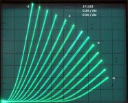
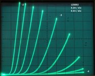
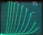
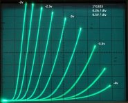
I have finally manage to assemble a Frankentracer from Michael Rothacher to trace my 2sk182es. I have 4 of them bought from pras. They were vgs matched.
1Y1323 and 190172 were labeled by Pras as 24v 2A=2.86v and 2.88v respectively
1Y3323 and 1Z0892 were labeled at 2.7v. Voltage and amp not specified so i guess 24v 2A.
Curves were traced at 0.25v interval. As we can see the first pair are close when we compare curves. Second are totally different.
Is that what mr. Pass ment when he say out of the pack curve wise? What do you guys think? Will it be possible to do something with that pair?
Attachments
Last edited:
Could just be due to some extra gate leakage stealing some input voltage, looking at the looping. What are you using to drive the step voltage? Low impedance?
You can always just try that one in a follower. 🙂
You can always just try that one in a follower. 🙂
Could just be due to some extra gate leakage stealing some input voltage, looking at the looping. What are you using to drive the step voltage? Low impedance?
You can always just try that one in a follower. 🙂
Here’s my setup. 24v 2A transformer connected to the variac. Exactly as per your schematic. Is that low impedance ?
Attachments

- Home
- Amplifiers
- Pass Labs
- While they last...