Now it is obvious - comparing both tweeter+filter impedance/frequency graphs side by side (post 16),
You hve the impednce plot in the first post.
Now it is obvious
<snip>
Measurements DO tells us how the loudspeaker will sound.
Nahh... Not sufficient.
There is obvious reason why FR, Impedance plot, phase response are not sufficient. It's because the sound is OFTEN/USUALLY determined by the limitation of the driver, in this case the tweeter. The tweeter has its unique distortion characteristics that demand unique treatment.
In the real world, we balance performance trade-offs. There is a reson why impednce compenstion is a popular solution. But it brings drawbacks. I have never liked the sound of impedance compensation. With the cheap tweeter used, the resistor across the tweeter will take the "heat". Most will prefer this sound I believe. Me? Obvious to me that I won't like both circuits.
Not so fast, becauseLook at again. I'm saying one of these circuits gives the amplifier a better load at supersonic frequencies. And that it matters for a good sound...
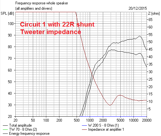
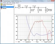
So Circuit 1 goes 25.9R (3.9R + 22R) at high frequencies.
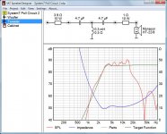
And Circuit 2 goes to infinity.
So, 10 R parallel to 25.9 R makes 7.2 R total for Circuit 1, andRotel has a tiny, as small as feasable really, Zobel of 10R and 0.1uF at the output.
10 R parallel to infinity makes 10 R total for Cicuit 2.
Sonic difference between 7.2 R and 10 R load at (ultra)supersonic frequencies? Negligible.
No, in the first post there are impedance plots of the whole systems only. More revealing are the impedance plots of the tweeter+(high-pass)filter alone - which is why I requested them.You hve the impednce plot in the first post.
In this case (obvious bad knee), impedance plots are sufficient to tell us which circuit sounds better.There is obvious reason why FR, Impedance plot, phase response are not sufficient.
No, in the first post there are impedance plots of the whole systems only.
The system (total) impedance at HF is determined by the tweeter and at LF is determined by the woofer.
In this case (obvious bad knee), impedance plots are sufficient to tell us which circuit sounds better.
Why the knee should be bad. Tweeter coil will make system impedance rising at very high frequency. Impedance correction will level this at certain point where you see the "knee".
But the main point why you cannot use it to determine sound quality is because the impedance is not the bottleneck.
Not having heard either but my opinion is that it also depends on how it does a step function. Does it resemble transient perfect with a right triangle? That makes a big audible difference.
Yes, but total impedance alone may put veil on some important clues. On the other hand, total impedance together with total phase vs frequency can reveal some important flaws.The system (total) impedance at HF is determined by the tweeter and at LF is determined by the woofer.
System7, please post the total impedance/phase graphs for both circuits.
Bad knee indicates some unwanted resonances in the time domain, which translates in a bad quality sound. That is the bottleneck indicated in the impedance graph.Why the knee should be bad.
But the main point why you cannot use it to determine sound quality is because the impedance is not the bottleneck.
On the other hand, total impedance together with total phase vs frequency can reveal some important flaws.
Like phase turn at low impedance? Surprisingly the impedance are above 8 ohm at all frequency.
Bad knee indicates some unwanted resonances in the time domain, which translates in a bad quality sound. That is the bottleneck indicated in the impedance graph.
This is system impedance due to crossover, not driver impedance in free air. Nonlinear distortion will always be there, whatever the shape of the system impedance.
But I agree that from impedance perspective, that one should sound better. But I think it is not the determinant factor to make it obviously sound better.
Exactly! And that is the main problem here.This is system impedance due to crossover, not driver impedance in free air.
I quite agree that flat impedance, perfect frequency response and all that can't do any harm.
But there really is no problem with this kink in tweeter impedance. It is there because this is a (flat power response) BW3 filter which effectively boosts the output at the 3kHz crossover whilst being 90 degree phase with the woofer to keep frequency response flat.
If I did it LR2 or LR4 it would be flatter. But it's in a region where the solid state amplifier feedback can cope easily. Not the reason one circuit sounds better than the other IMO. I'm saying it's an amplifier effect.
High speed amplifiers for audio
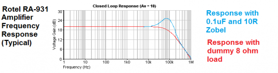
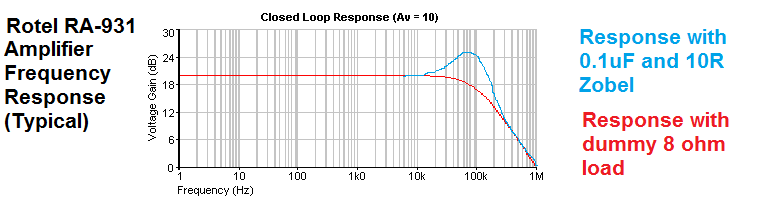
You need to know that regular transistor amplifiers have actually run out of gain completely by say, 20kHz. So there is virtually NO feedback to reduce distortion. This is why amplifiers are very load dependent at high frequency and their stability matters. At 100kHz distortion is enormous into open circuit.
Rotel have added that little 10R and 0.1uF Zobel to keep it just stable into open circuit. But really, it's designed for 8 ohm dummy load.
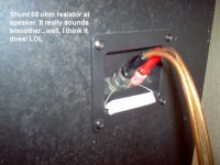
Maybe we now understand why that 68R resistor across the speaker terminals actually does do something! 😎
But there really is no problem with this kink in tweeter impedance. It is there because this is a (flat power response) BW3 filter which effectively boosts the output at the 3kHz crossover whilst being 90 degree phase with the woofer to keep frequency response flat.
If I did it LR2 or LR4 it would be flatter. But it's in a region where the solid state amplifier feedback can cope easily. Not the reason one circuit sounds better than the other IMO. I'm saying it's an amplifier effect.
High speed amplifiers for audio
You need to know that regular transistor amplifiers have actually run out of gain completely by say, 20kHz. So there is virtually NO feedback to reduce distortion. This is why amplifiers are very load dependent at high frequency and their stability matters. At 100kHz distortion is enormous into open circuit.
Rotel have added that little 10R and 0.1uF Zobel to keep it just stable into open circuit. But really, it's designed for 8 ohm dummy load.
Maybe we now understand why that 68R resistor across the speaker terminals actually does do something! 😎
Attachments
Lynn Olsen said something relevant on this forum about amplifier load at high frequencies a while back:
Alex
I always start with the most-accurate inductance compensation for every driver, extending it well beyond the audio band. Back at Audionics, I once designed a speaker with a flat impedance curve out to 1 MHz, just for grins - it only took 4 extra parts, so why not? The Audionics CC-2 had plenty of phase margin, but very few other amplifiers did, and these sounded less stressed and more natural with a resistive load in the 70 to 300 kHz range. It was easy enough to do an A/B test (flip a switch for the two RC networks), and the flat-impedance version sounded better with the competing amplifiers. On the CC-2, it made no difference.
Alex
Oh yes. Inferior amplifiers need inferior speakers. I don't even know inferior amps exist (hyperbole). Only the THD is good in the Rotel (and you know why).
Alex M, that Lynn Olson article on impedance matching is very good. Thankyou.
http://www.diyaudio.com/forums/multi-way/100392-beyond-ariel-722.html
Time for the answer, which only 30% of us got. This test was with the Rotel RA-931 amplifier, a cheap but mature and solid Class AB design. 🙂
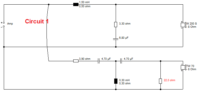

Circuit 1 with the 22R is the better sounding circuit. It is very detailed at the top end and goes loud comfortably. Any limitations in dispersion and HF are measurably down to the cone tweeter IMO.
Circuit 2 with the 1R series sounds bright and lively at the top end, but has an uncomfortable fuzzy distorted sound. All too common and familiar in irritating sounding speakers. And we've all had a few of those.
http://www.diyaudio.com/forums/multi-way/100392-beyond-ariel-722.html
Time for the answer, which only 30% of us got. This test was with the Rotel RA-931 amplifier, a cheap but mature and solid Class AB design. 🙂
Circuit 1 with the 22R is the better sounding circuit. It is very detailed at the top end and goes loud comfortably. Any limitations in dispersion and HF are measurably down to the cone tweeter IMO.
Circuit 2 with the 1R series sounds bright and lively at the top end, but has an uncomfortable fuzzy distorted sound. All too common and familiar in irritating sounding speakers. And we've all had a few of those.
I am still not convinced with your explanation.You need to know that regular transistor amplifiers have actually run out of gain completely by say, 20kHz. So there is virtually NO feedback to reduce distortion. This is why amplifiers are very load dependent at high frequency and their stability matters. At 100kHz distortion is enormous into open circuit.
Rotel have added that little 10R and 0.1uF Zobel to keep it just stable into open circuit. But really, it's designed for 8 ohm dummy load.
Circuit 2 with the tweeter is not an open circuit (R=infinity) at high frequencies! According to your simulation, there is 15 R impedance at 20 kHz. At 100 Hz impedance will be higher, but far from infinity. Besides, Visaton tweeter starts to roll of down at 15 kHz, so I have three questions: Which musical instruments have 100 kHz overtones, how on earth Visaton/Monacor tweeter can reproduce 100 kHz "enormous distortion" and how your ears can hear that distortion at 100 kHz?!
My experience is that impedance knees (as on Circuit 1) have disastrous effect on sound quality.
But some love distorted sound ("very detailed at the top end") at the presence region (3 - 5 kHz). De gustibus non est disputandum.
Last edited:
Steve,
I think you're cutting short a well designed SS amp when you say it's out of gain by the time it hits 20k, maybe your Rotel is.
Perhaps you need to read-up on amp design by guys like Bruno Putzey or Erno Borbely or John Curl etc etc. I think you'll find that a well designed SS amp can still have gain far beyond 20khz.
I kinda agree with WTS, I'm not familiar with that particular amplifier, but id be shocked if it was at its -3dB corner gain by 20kHz, or even 40kHz.
In that case, feedback is maintained within the audible range and slightly beyond. Load impedance at HF is still important. And I guess it is possible that what may be heard is subharmonics from IMD rather than THD, whose fundamental is above the audible range.
I just don't think that there's enough difference between cases to be heard. Caveat being I haven't heard that amplifier - speaker combination, and tried the same experiment
So I stay with my initial feeling - another System7 curveball. Entertaining and intelligently witty as usual ��
If the Rotel is so sensitive....modify the amplifier. Or get a better one. Im going out on a limb a little and I could easily look dumb, but I'm used to it!
I'm pretty sure a typical chipamp can achieve a typical bandwidth with typical gain which is 2x, 3x the 20-40kHz range specified. Its just restricted to perhaps 50kHz -3dB point for stability.
But
System7, I'm not sure, maybe you've missed a trick?
Didn't manufacturers of lesser quality loudspeakers, of 16 Ohm (sometimes64 Ohm) just whack a small value ceramic capacitor across the input terminals, to do the same thing?
Say.... 1000pF to.... 22nF....at a guess.
What does that simulate like? As a 3rd circuit if you like.
Last edited:
Or more to the point, what difference does it make?If the Rotel is so sensitive....modify the amplifier.
I'm pretty sure a typical chipamp can achieve a typical bandwidth with typical gain which is 2x, 3x the 20-40kHz range specified. Its just restricted to perhaps 50kHz -3dB point for stability.
Opamp-based class AB amp designs are hard to make stable, especially if using fast opamps. There's a trick but...
Or more to the point, what difference does it make?
Even with good amplifiers, recording materials, speaker crossover designs and drivers, most people will prefer the effect of the shunt resistor (especially when the tweeter is capable of 40kHz like the dynaudios). It seems the less perfect situation here will exaggerate that benefit.
To me, it's like an L-PAD. If I don't like the effect of an l-pad to sound, can I avoid it in a speaker design to achieve the same goal (reduce tweeter response)? Moving the attenuation resistor to the input side is usually sufficient.
Last edited:
Circuit 2 ... has an uncomfortable fuzzy distorted sound.
Probably HF oscillations of the amp. A peak of 5 dB means the phase margin of the Rotel amp simply is too low. The step response without load must look terrific.
Don't blame circuit 2, properly designed it could be fairly equal to circuit 1. However, your version 2 isn't, the attached simulations show it's actually brighter than version 1.
Attachments
- Status
- Not open for further replies.
- Home
- Loudspeakers
- Multi-Way
- Which crossover sounds better?