"Normal magnetization curve", dashed line in post #25 is obtained with pure DC currents. You apply certain fixed H (ampere-turns) in the range, say from -1 to +1, and measure corresponding B. Under DC measurements like this there is NO hysteresis. Hysteresis only appears when H changes in the course of measurement. Solid lines in that graph are obtained with AC. As you can see, in the case of AC magnetization, the 0,0 point is never crossed.
The upper curve on my graph is the magnetization curve of a SE transformer that represents DC bias and AC signal.
The upper curve on my graph is the magnetization curve of a SE transformer that represents DC bias and AC signal.
jtgofish,
That is a great observation and that creates lots of questions.
There are a lot more factors than what you mention in your post.
I consider your post to belong in a completely different Thread.
Just my opinion.
It will become a bucket of worms, in my opinion; and we have enough subjects in this thread.
It started with a specific question about what causes Single Ended amplifiers to sound like they do (not that all SE amps sound the same).
Just a few Generalizations:
Both SE and PP tube amplifiers can have:
Essentially Resistive Triodes
Essentially Current Source Pentodes and Current Source Beam Power tubes.
Global negative feed back that can change an essential current source into an essential resistive source
Given enough global negative feedback, you essentially have a Voltage source.
What would you like a tube amplifier to be?
"All Generalizations Have Exceptions" - me
sser2,
Good points!
Thanks!
Perhaps we should only use Air Core Transformers.
Wouldn't all that Hysteresis go out the window?
Thanks for reminding me, my speakers have crossover coils that use magnetic cores, I want to replace them with Air Core inductors.
I guess all that Hysteresis was just my error (and my pun).
My lessons in the magnetic hysteresis domain were before most readers of this post were born.
Then I moved on to RF with Air coils, and then to Waveguides with no coils or wires, just a 100Ghz diode at one end, and a 500GHz harmonic at the other end.
Now, I am off to chase other rabbits down the hole.
Last edited:

6A3sUmmer:
Hysteresis may seem horrific, but by no means all iron core transformers are grossly distorting. One example could be an interstage transformer working into infinite load (grid of a driven tube). Magnetizing current distortion will only cause signal voltage distortion if the load impedance is low (distorted current passing through resistor generates distorted voltage across it). Under conditions of low source impedance and high load impedance, distortion due to transformer core may be vanishingly low. This is very well explained in Crowhurst article on transformer distortion.
One more concern is the nature of the core material. In the graph below, there are B-H curves of silicon steel and 80% Ni permalloy on the same scale. Compared to silicon steel, permalloy has vanishingly low hysteresis; its magnetization is almost linear.
But, but, but, DC bias has a horizontal component. It (by definition) moves zero signal operating point of the OPT up (or down) the normal ("DC") magnetization curve.The upper curve on my graph is the magnetization curve of a SE transformer that represents DC bias and AC signal.
In early days there were magnetic tape recorders that used DC rather than ultrasonic AC to bias the tape. Bias in tape recording is needed because of the non-monotonic behavior of iron's B/H normal magnetization curve. DC bias proved too noisy, but otherwise works.
All good fortune,
Chris
Thank you for correcting me, Chris. Indeed, the hysteresis loop should be shifted not only upwards, but to the right as well. But the shape of the loop remains the same.
Mag tape is a different beast than transformer core material. Tape is more of a hard ferromagnetic (like permanent magnet) than soft core iron with very low remanence.
Mag tape is a different beast than transformer core material. Tape is more of a hard ferromagnetic (like permanent magnet) than soft core iron with very low remanence.
sser2,
and
Chris,
Thanks, sser2!
I am beginning to understand more about output transformer distortion . . .
Perhaps that is why I like my later amplifier designs, even with no negative feedback from the transformer primary or secondary . . .
I use: Triode wired beam power tubes (low to mid plate rp); relatively high primary impedance; low power from the push pull tubes, so low output power (low current) to the speaker load; and speakers with relatively friendly mid and high impedance across the audio frequency range.
Thanks Chris!
I am reminded of some tape recorders that used a magnet for bias; and some recorders that used a magnet to erase the tape.
Interesting low cost solutions of the day
I think one problem with magnets used that way, was that the record/playback head became magnetized too . . . not a very good idea.
Good Listening Everybody!
Last edited:
Such an amplifier was patented in Australia in 1999 by Graeme J Cohen.Build 2 SE amplifiers.
But it appears the patent was withdrawn in 2002. Probably a problem with some obscure prior claim.
The lawyers always come out on top.🙄
http://www.ipaustralia.com.au/applicant/cohen-graeme-john/patents/AU1996042023/
An article covering the amplifier was published in Glass Audio of March 1996,
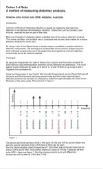
Cohen among several other papers published a very interesting technique to measure both THD & IMD at the same time.
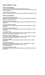
I've used this method several times it is very effective. There is a listing of other work by Cohen on the last page of that document.👍
Attachments
jhstewart9,
Thanks for the great dissertation from Mr. Cohen!
Boy!
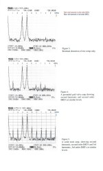
Look at the comparison of the test equipment residual distortion; then the grounded grid amp distortion, then the solid state amp's bad distortion.
And, you made me think of the old Ma Bell tests (most likely designed by Bell Labs).
An FM microwave link with multiple channel packs (0-4k; 4-8k; 8-12k; etc.)
At the transmitter, take out one of those channel packs, the 4-8k for example.
Then the intermodulation and harmonics of the 0-4k and the 8-12k channels fills in the 4-8k channel at the receiver end; the amount of that fill in power gives the distortion of the lower and upper channels into the "empty" channel.
Perhaps a precursor to the adjacent channel and alternate channel tests of a digital transmitter.
Lots of spectrum analyzers sold into the cell phone industry . . . amplifiers, base stations, and cell phones.
At first, the amplifier manufacturers did not want to have to measure EVM, Error Vector Magnitude.
But then the system designers wanted the manufacturers of the modulators and amplifiers to specify EVM.
That all adds up according to Either Root Sum Square, or more according to Murphy's Law, depending on the phase of the moon.
Lots of special spectrum analyzers sold to those manufacturers: DAC/Modulators, amplifiers, and the finished products of both base stations and cell phones.
Thanks for the great dissertation from Mr. Cohen!
Boy!
Look at the comparison of the test equipment residual distortion; then the grounded grid amp distortion, then the solid state amp's bad distortion.
And, you made me think of the old Ma Bell tests (most likely designed by Bell Labs).
An FM microwave link with multiple channel packs (0-4k; 4-8k; 8-12k; etc.)
At the transmitter, take out one of those channel packs, the 4-8k for example.
Then the intermodulation and harmonics of the 0-4k and the 8-12k channels fills in the 4-8k channel at the receiver end; the amount of that fill in power gives the distortion of the lower and upper channels into the "empty" channel.
Perhaps a precursor to the adjacent channel and alternate channel tests of a digital transmitter.
Lots of spectrum analyzers sold into the cell phone industry . . . amplifiers, base stations, and cell phones.
At first, the amplifier manufacturers did not want to have to measure EVM, Error Vector Magnitude.
But then the system designers wanted the manufacturers of the modulators and amplifiers to specify EVM.
That all adds up according to Either Root Sum Square, or more according to Murphy's Law, depending on the phase of the moon.
Lots of special spectrum analyzers sold to those manufacturers: DAC/Modulators, amplifiers, and the finished products of both base stations and cell phones.
Last edited:
For all the fans of WE toobz do yourselves a favor & spend a few $$$ to get a copy of the WE Tube Data book.
All 242 pages of it. It was reproduced in full by Antique Electronic Supply in Tempe, AZ about 25 yrs ago when I got my copy.
They may still have stock or try the used books online stores.
All 242 pages of it. It was reproduced in full by Antique Electronic Supply in Tempe, AZ about 25 yrs ago when I got my copy.
They may still have stock or try the used books online stores.
Attachments
imho, all of them.Hi,
the title has been chosen to explicit that this is a pour-parler kind of thread, to better understand the preferences many people have on the SET amps.
I would like indeed to ask your opinion on which characteristics make SET amps so special compared to other kind of amps.
Is the predominance of 2nd (and then 3rd) harmonic distortion?
Is the absence of gnfb and so a different saturation behaviour and recovery after peaks?
Is the relatively low DF, generally between 2 and 4, and the consequent interaction with the speaker (more low-highs, even if less controlled)?
Others?
Thanks in advance.
One more thought as we leave the discussion of the B-H Curve.
The DC magnetization curve (dotted line in Post # 25) that has a jog right near where the DC current is slightly negative, then zero, then slightly positive.
Half of that jog is not even there in a Single Ended output transformer. Right?
After all, the SE amplifier has a Quiescent DC current, and that primary current is always in one direction.
We never reverse the polarity of the DC current in an SE amplifier (at least not if it is operating properly).
And that is the part of the magnetization curve that had me confused, when it came to the magnitization as we set the DC current up and down the curve.
I did not remember the bi-directional - to zero to + current jog for SE operation, it is not there.
Only the zero to +; (Or the zero to -) portion of the DC. magnetization curve is there.
Not that the DC magnetization curve really affects the dynamic Hysteresis curve of Both SE and PP amplifiers.
Look at it this way . . .
The DC magnetization curve is only in 1 Quadrant, if the polarity of the DC does not change.
And the AC Hysteresis of SE and PP is in 4 Quadrants.
Just how I look at it now.
Last edited:
hpeter,
OK. Back on subject.
How about many SE amplifiers that use an Air Gapped Output Transformer?
Versus many PP amplifiers that use an interleaved (Non Air Gapped) Output Transformer.
"All Generalizations Have Exceptions" - me
Including the many various constructions of SE and PP transformers.
Parafeed, anybody?
(one topology of SE)
Typically, Parafeed has: Both Air Gapped laminations, AND Non Air Gapped laminations.
(An Air Gapped Choke makes a much more Energy Efficient Plate load, versus an electronic CCS).
Last edited:
I remeber @SpreadSpectrum ‘s Corona amp has a very high DF for a SE without gnfb. I hope he will partecipate because I would like to have his impressions on this particular amp compared to other SE amps.
zintolo,
You said: "is there any reference for a good ratio at 1 Wrms?"
Ratio of what?
Did you mean a ratio of 2nd harmonic distortion to 3rd harmonic distortion?
Put that question in the context of a complete playback system:
System 1, 1 Watt from the amplifier, and a loudspeaker that is 95dB efficient, that is 95dB of sound.
System 2, 1 Watt from the amplifier, and a loudspeaker that is 87dB efficient, that is 87dB of sound.
Your ears will be working on completely different sound levels of Fletcher-Munson family of curves.
Or, did I mis-understand your question?
@6A3sUMMER you completely got the point and expanded the poi tof view as usual. I was indeed thinking such a low wattage because my Klipsch are very efficient. Thanks.
zintolo,
I was tired and sleepy when I answered you last night.
But this morning I had an additional, and hopefully helpful thought, related to your excellent question.
An example of distortion of an amplifier:
(We will only use signal levels that are in the well behaved region of the amplifier (not near clipping, not at clipping, and not where some circuit is in a weird or un-controlled area).
The example amplifier:
(and in a slightly different way to look at it)
A 10 Watt amplifier gets used at relatively low power:
With the original sine wave test tone output of 1 Watt, 2.828Vrms into 8 Ohms.
But the harmonic distortion addss some power too.
The 2nd harmonic distortion is 1% additional signal voltage; and the 3rd harmonic distortion is 15dB less than the 2nd harmonic distortion, so the 3rd is 0.178% additional signal voltage.
1% is 0.01, or -40dBc relative to the 1 Watt original sine wave, that is 0.0001 Watt 2nd harmonic distortion (1/10,000 Watt). 0.01 milliwatt.
And, 0.178% is -55dBc relative to the 1 Watt original sine wave, that is 0.00000316 Watt 3rd harmonic distortion (3.16/1,000,000 Watt) 3.16 Microwatt.
We now have 1 Watt original sine wave, 0.01 milliwatt 2nd harmonic D, and 3.16 Microwatt 3rd harmonic D.
Now, we increase the original sine wave test tone power to 2 Watts into the 8 Ohm load (An increase of 3 dB).
The original sine wave increases by 3dB, to 2 Watts
The 2nd harmonic distortion increases by 6dB, to 4 milliwatts, 34dBc, 2% HD
The 3rd harmonic distortion increases by 12dB, to 50 Microwatts, -43 dBc, 0.07% HD.
1 Watt, 0.01 milliwatt 1% HD, 3.16 Microwatt 0.178% HD
2 Watt, 0.04 milliwatt 2% HD, 50 Microwatt 0.07% HD
As you can see, the 2nd harmonic distortion increases faster than the original sine wave increases.
But the 3rd harmonic distortion increases much faster than the original sine wave, and faster than the 2nd harmonic distortion.
HD = A single harmonic's Harmonic Distortion (Not THD, that is Total Harmonic Distortion).
You can not add the two harmonic distortions to get THD.
That is another subject for another time or another thread.
I hope that helps.
Last edited:
@6A3sUMMER if I understand correctly we can consider the following backward calculus:
We have the data of the 300B when 2nd HD is at -26 dBc and 3rd HD is at -41 dBc.
Let’s go down 12 db to reach around 1 Wrms, considering a decrease of 2nd HD of 14 dB to reach -40 dBc (around 1%), 3rd could be reduced by around 28 dB to -69 dBc (around 0.035%).
So around 30 dB between 2nd and 3rd could be a reasonable point to chase at low wattages. All other harmonics being lower than that.
zintolo,
And other interested readers,
Good thinking!
But not so fast as some of the numbers you calculated.
I will make some corrections about the relationships of the fundamental, 2nd harmonic distortion, and 3rd harmonic distortion.
I am not sure, but It seems that you landed exactly on a particular setup of the WE 300B charts.
250V plate to filament; -45V grid to filament; 80mA plate current; 1500 Ohms primary; 5 Watts output; -26dBc 2nd harmonic; and -41dBc 3rd harmonic.
That is only 20 Watt plate dissipation, not real hot.
(I might be tempted to build that one myself; I still have two One Electron UBT-1 output transformers (1600 Ohms primary), and they have really good square wave response).
Now, the relation of the fundamental; versus the 2nd, and the 3rd harmonic distortions.
This is just a generalization, think of a 2 stage SE amplifier that has a distortionless single triode input/driver tube.
That way, we are considering only the 300B distortion.
Think of the Fundamental as a car going 100MPH; the 2nd harmonic distortion as a car going 200MPH, and the 3rd harmonic distortion as a car going 300MPH.
Start with the amplifier power output extremely low, there is only the first car: the fundamental, the 100MPH car just got started.
But the 2nd and 3rd cars are still in the gates.
Now we increase the amplifier output power a little, and so . . .
we let the 2nd car out of the gates (at 200MPH, it eventually could catch up to the 1st car).
As we increase the amplifier output power even more, we are letting the 3rd car out of the gates (at 300MPH, it eventually could catch up to the 1st car).
As you can see, the 2nd car is 100MPH Faster than the 1st car, the difference is 100MPH.
And, the 3rd car is 200MPH Faster than the 1st car, the difference is 200MPH.
Conclusion:
As we increase the amplifier power output, the 2nd harmonic distortion becomes visible first, and with even more output power the 3rd harmonic distortion becomes visible.
But when you can see both of them, if we increase the power out even more, the 3rd harmonic distortion increases faster than the 2nd harmonic distortion increases.
Now for some numbers:
5 Watts is 7dB more than 1 Watt
5 Watts;
2nd harmonic -26dBc;
3rd harmonic -41dBc.
Ratio of 2nd to 3rd harmonic distortion is 15dB.
1 Watt;
2nd harmonic -26dBc - 7dB = -33dBc; Yes, -7dB (the 200MPH car goes 100MPH faster than the 100MPH car).
3rd harmonic -41dBc -14dB = -55dBc. Yes, -14dB (the 300MPH car goes 200MPH faster than the 100MPH car).
Ratio of 2nd to 3rd harmonic distortion is 22dB.
Conclusion:
We decrease the output power by 7dB; and the ratio of 2nd to 3rd harmonic distortion also changed by 7dB.
I hope that makes it clear for everybody.
If anybody wants to do some reading on the subject, look up the 2nd Order Intercept, and the 3rd Order Intercept.
Caution: In real life, they never reach the Intercept point, but the slopes of the curves in the well behaved region is the same as if there were real 2nd and real 3rd order Intercepts,
Such a handy tool it is.
This works for harmonic distortion, and works for Intermodulation distortion (In the well behaved regions of power output).
Whew! That was a lot of work for me.
Last edited:
- Home
- Amplifiers
- Tubes / Valves
- Which characteristics are more influent on the sound of SET amps?