JoeBob said:Adding an L would smooth things out, but are there any obvious downsides I don't know about?
On a SS amp with low voltage & high current you have to worry about the voltage drop across the choke (and the power it will have to dissipate).
dave
JOE DIRT® said:try the test out with a random signal (pink noise)
I don't know what additional insight one gains by doing this. Simulations, by definition, aren't real and 100% reflective of reality. But as long as it captures the key "themes" of the issues one is interested to study, they have done their jobs.
And in this case, I think pedja's simulation so far has answered the questions vs. cap size. Using pink or purple or white noises does not foundamentally or directionally change the conclusions we have so far.
It seems to me, after having gone through all the charts, that it is clear that unless there are some particular designs in the lm chip, it is unlikely that it will benefit from small PS caps.
AFAIK, Pi filters are really good for class A amps where the current draw from the psu is a constant value. The whole point with a choke is to not allow sudden rushes of current through.
In an amp with a class AB output stage such as the LM3875 (although all stages up until the output stage appear to be current sourced class A stages) the need to pull a quick slug of current from the power tranny would be compromised by the presence of a choke.
Yes a choke would cut HF PSU noise but I think it would kill dynamics by destroying the fast recovery attributes of the PSU as well. (assuming that one believes in the benefits of a fast recovery PSU)
Drew
DrewP said:AFAIK, Pi filters are really good for class A amps where the current draw from the psu is a constant value. The whole point with a choke is to not allow sudden rushes of current through.
In an amp with a class AB output stage such as the LM3875 (although all stages up until the output stage appear to be current sourced class A stages) the need to pull a quick slug of current from the power tranny would be compromised by the presence of a choke.
Yes a choke would cut HF PSU noise but I think it would kill dynamics by destroying the fast recovery attributes of the PSU as well. (assuming that one believes in the benefits of a fast recovery PSU)
Drew
Drew,
With the choke filter, it's the last cap that furnishes the "slug of current". Since the diodes only conduct 20% or less of the time, the xformer couldn't do it for 80% of the time anyway, even if there is no choke.
Jan Didden
It might be interesting to repeat the simulations with a low-value resistor (say 1 or 2 ohms) between the diodes and the filter caps.
This will lower the mean voltage on the caps (and so the charging pulses should be longer and less spiky), but without the voltage ripple of the small capacitor version.
Cheers
IH
This will lower the mean voltage on the caps (and so the charging pulses should be longer and less spiky), but without the voltage ripple of the small capacitor version.
Cheers
IH
ALW said:
You should do an FFT of your raw PSU if you think it's just 100Hz 😉
Andy.
I have! Or just connect a little speaker with a suitable DC blocking cap across your reservoir cap and listen to it. Then ponder that you must be listening to that minus x dB down.
Have you ever done it with a choke input PSU ? Very instructive! Nice enough to hum along to.
😉
But this whole discussion about reservoir caps can only be resolved by doing the obvious.... try it. Even better vary its value as we often vary other parameters and then listen to it. Why should these be any different?
Personally I suspect the whole thing come down to dynamic behaviours that are very difficult to predict and even more difficult to model. The way it affects the ability to portray pitch and pace in the mid-bass area alone seems to point to a possible resonant interactions between the dynamic behaviour of the circuit and the ability of a frequency based LF PSU to hang in there. The PSU does not have a constant source impedance (even with regulators difficult to achieve) and the constantly changing load imposed on it... and a merry dance indeed!
But don't bother figuring it out when the solution is: Just experiment - it will be better for your sanity.
Batteries anyone? How about setting up a trickle charged batteries where the averaged trickle is set above the averaged out (over time) current requirement? (Then allow for suitable peak current ability and test PSU Z on peak load) I have done it to Turntable power supplies (TT using DC motors). Could work a treat?
Certainly the noise floor would be dramatically lower, that should have other benefits like reduced haze and greyness this potentially adds to the sonics of most amps.
I make some interesting tube amps that use an infinitely high AC Z, an inverse bandwidth power supply. The amp circuits rides the power supply (and hence is isolated) and it is the power supply itself that is left to sort it out. There are many ways to tackle same or different problems. Maybe that is why we like our chosen toys ?
Joe R.
With the choke filter, it's the last cap that furnishes the "slug of current". Since the diodes only conduct 20% or less of the time, the xformer couldn't do it for 80% of the time anyway, even if there is no choke.
Yes, the cap provides the slug to the amplifier chip but then how quickly is it refilled?
On our 50hz (Australian) supply, if as stated (and I have every faith that this is true) the diodes conduct for 20% of each half wave (which occurs 100 times a second). So, you're trying to top up the second PSU reservior (the one after the choke) with a short term current pulse that lasts 2ms (20% of 10ms).
So once the final reservior is depleted of its charge, how quickly can it be refilled with a choke in the way?
You folks out there who love doing simulations and drawing beautiful curves and graphs for us, please simulate a 100hz square wave with 2ms on pulses and 8ms off pulses trying to flow through a series choke being fed by a low impedance transformer and show me how compromised and fubarred the output to the final psu cap after the choke is.
My prediction is that the result will not be fast refill of the reservior.
Drew
Listening to Power supplies...
Would probably work best if the amp was amplifying. Listening to the steady state noise probably isn't that instructive.
The original Gain has the transformer and diodes in a separate box. I wonder how much the characterisics of this connection scheme (impedence and inductance of the wiring etc.) have been used to alter the characteristics of the high frequency burst as seen by the power opamp.
Joe Rasmussen said:But this whole discussion about reservoir caps can only be resolved by doing the obvious.... try it. Even better vary its value as we often vary other parameters and then listen to it. Why should these be any different?
there is no question an actual prototyping will give the ultimate answer but if simulation can get us 80% of it using 20% of the resources, it is a pretty good starting point.
the proliferation of simulation in recent years is a good supporting evidence of that.
Joe Rasmussen said:Batteries anyone? How about setting up a trickle charged batteries where the averaged trickle is set above the averaged out (over time) current requirement? (Then allow for suitable peak current ability and test PSU Z on peak load) I have done it to Turntable power supplies (TT using DC motors). Could work a treat?
Joe R.
maybe the opposite is more useful in an amp. batteries have high output resistence. so one way to go might be to use a battery in parrallel with a conventional PS (isolated with a diode) that outputs slighly below or at the battery's voltage. Under slight load, the battery is the only one contributing. Great.
Under heavy load, the battery's voltage drops, and the conventional PS, with its low impendence, starts to kick in, providing the neccessary "headroom".
DrewP said:My prediction is that the result will not be fast refill of the reservior.
Drew
I agree with your intuition. a pi filter is a low-pass filter. and it will not react quickly with a high-frequency current drain.
I will do some simulation later today.
On the idea of using a low-value resistor in place of the inductor in a pi filter. I have seen it mentioned 20 or 30 years ago (I am quite sure that some tube amps actually use this set-up for filament).
But I am not quite sure how well it works with amps as you essentially increased the output impedence of a PS. during the 80% of the time when the cap is discharging, that's like increasing the ESR of that cap substantially. It may induce parasitic oscillation as well.
But I am not quite sure how well it works with amps as you essentially increased the output impedence of a PS. during the 80% of the time when the cap is discharging, that's like increasing the ESR of that cap substantially. It may induce parasitic oscillation as well.
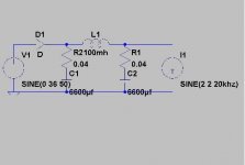
this is the output for no inductor (I think I set the inductor value to 0.00001mh).
the green curve is the charge current going through the diode (right scale), and the blue one is the voltage over the load (right scale).
as you can see, voltage fluctuats from 32 - 35v, or 10%.
note that the "fuzzy" voltage line is due to driving a 20khz current source.
the green curve is the charge current going through the diode (right scale), and the blue one is the voltage over the load (right scale).
as you can see, voltage fluctuats from 32 - 35v, or 10%.
note that the "fuzzy" voltage line is due to driving a 20khz current source.
Attachments

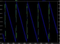
here is the case with a 100mh inductor.
the voltage fluctuates from 32v to 33 v (3% variation). the thick voltage line, again, is a 20khz signal on top of the basic 50hz carrier.
it does seem to be that case that using an inductor helps smooth out the 50hz carrier but unfortunately, the 20khz variation gets a low worse: 0.2v variation vs. almost nothing in the prior case.
conclusion? inductors are better for PSs that deal with more steady load.
Attachments
measurement summary
I promised some measurement results, so here they are. They are probably not as extensive as you had hoped.
First, the amp vitals. LM3875 inverted configuration, dual EI 24VAC transformers in a separate box, vanilla 400V, 35A diode bridges, 2200uF caps next to the chips.
The main test I ran was to place an 8ohm resistor across the +/- terminals of one of the diode bridges. IIRC, the positive rail, although with hindsight the negative rail would have been a better choice given the 30 dB worse PSRR at 1 kHz. Qualitatively, with my ear very near the speaker, I could hear little difference in hum/hiss even though one rail had been dropped asymmetrically to 22.7V from 35V and had a huge 5V(p-p) 120Hz ripple.
Unfortunately, the dynamic range of the scope was only about 80 dB, so it was not possible to resolve really low level detail.
Freq. Level
------ --------
0 Hz 0 dB (22.7V)
60 Hz below noise floor at -60 dB
120 Hz -22 dB (1.8Vrms)
240 Hz -47 (0.1Vrms)
360 -48
480 -69
600 -63
720 -70
840 -79
960 -76
So, given the much larger current drain, these values match Pedja's sims fairly well. I didn't try a measurementat high frequency to see diode RF noise.
I then removed the 8ohm load resistor and played a 1 kHz test tone. Significant harmonics of 1 Khz appeared on the supply rail due to the split supplies, although at a lower level than the -50dB of the 1Khz signal (output about 1 Watt). 4 kHz was below the noise floor. These harmonics could conceivably give the chip PSRR problems at high frequencies and high output levels.
Jeremy
janneman said:
With the choke filter, it's the last cap that furnishes the "slug of current". Since the diodes only conduct 20% or less of the time, the xformer couldn't do it for 80% of the time anyway, even if there is no choke.
I have good experiance using input chokes on class A amps, they get as clean as you ever thought and it's a test that I would do with these class B chip amps provided I had a test bed for it and extra secondary voltage needed for this setup.
Looking for a good sound I would test different cap sizes and types, and use something like 10 to15 mH gapped chokes
Thing is I have not built this chip amp yet to do some testings, when I do I'll report back.
Keep on with these nice ideas, pedja's modellings are very enlighting even for my humble understanding.
Re: measurement summary
so essentially having huge amps doesn't help much (diminishing rate of return).
I got similar results on a discrete amp I am working on. Injecting 5v/50hz ripples to the supply rail (otherwise 36vdc) induced an increase of 0.004% in THD on an 8ohm load, with just some simple RC decoupling for the input and vas stages.
I basically concluded that 6600uf per rail will be sufficient for my application, even for driving 4ohm loads.
I did a quick simulation of the "audioamp" circuitry in switchercad. with a 2vac/50hz ripple in the positive supply rail (10vdc), thd is 0.2759%, vs. 0.2708% without the ripple.
this is a pretty typical simple discrete amp, without any current source or curren mirrors. so real amps should perform a lot better than this.
kropf said:Freq. Level
------ --------
0 Hz 0 dB (22.7V)
60 Hz below noise floor at -60 dB
120 Hz -22 dB (1.8Vrms)
240 Hz -47 (0.1Vrms)
360 -48
480 -69
600 -63
720 -70
840 -79
960 -76
Jeremy
so essentially having huge amps doesn't help much (diminishing rate of return).
I got similar results on a discrete amp I am working on. Injecting 5v/50hz ripples to the supply rail (otherwise 36vdc) induced an increase of 0.004% in THD on an 8ohm load, with just some simple RC decoupling for the input and vas stages.
I basically concluded that 6600uf per rail will be sufficient for my application, even for driving 4ohm loads.
I did a quick simulation of the "audioamp" circuitry in switchercad. with a 2vac/50hz ripple in the positive supply rail (10vdc), thd is 0.2759%, vs. 0.2708% without the ripple.
this is a pretty typical simple discrete amp, without any current source or curren mirrors. so real amps should perform a lot better than this.
Re: measurement summary
Hi Jeremy,
Thanks for the results. One thing I forgot to post earlier: all the graphs with log Y axis I posted are relative to 1V (0dB) and not to the carrier. So, the absolute levels in your measurements are showing better figures then they would be if scaled as those in my simulations. However, since the current drawn in your case was notably higher (fluctuates between 3A and some 4.3A if I am not mistaken) the things still could fit to each other.
I ran shortly that 2200uF/8 Ohms load case and the spectral content of the harmonics relates very well to your measurements, though cap’s ESR and parasitic series resistance could change this content somewhat. But what puzzles me is that you get 5V p-p swing around the 22.7V. I see swing between some 23V (or 22.7V you mentioned) and 34V (it can’t reach 35V anymore even at the peak) so it seems to me I am missing something about your circuit.
(Generally I also believe that our results are likely in agreement, just need to synchronize them.)
Yup, something like harmonic distortion at PSU lines. And seems to me like there is an IMD here also.
Pedja
Ps: Two more notices about the previous graphs that I forgot to give along the road. All FFTs are done for 10th cycle (90ms-100ms period). If some ask why not the logarithmic freq axis - MicroCap can’t show the logarithmic X axis to display a negative values.
Hi Jeremy,
Thanks for the results. One thing I forgot to post earlier: all the graphs with log Y axis I posted are relative to 1V (0dB) and not to the carrier. So, the absolute levels in your measurements are showing better figures then they would be if scaled as those in my simulations. However, since the current drawn in your case was notably higher (fluctuates between 3A and some 4.3A if I am not mistaken) the things still could fit to each other.
I ran shortly that 2200uF/8 Ohms load case and the spectral content of the harmonics relates very well to your measurements, though cap’s ESR and parasitic series resistance could change this content somewhat. But what puzzles me is that you get 5V p-p swing around the 22.7V. I see swing between some 23V (or 22.7V you mentioned) and 34V (it can’t reach 35V anymore even at the peak) so it seems to me I am missing something about your circuit.
(Generally I also believe that our results are likely in agreement, just need to synchronize them.)
I then removed the 8ohm load resistor and played a 1 kHz test tone. Significant harmonics of 1 Khz appeared on the supply rail due to the split supplies, although at a lower level than the -50dB of the 1Khz signal (output about 1 Watt). 4 kHz was below the noise floor. These harmonics could conceivably give the chip PSRR problems at high frequencies and high output levels.
Yup, something like harmonic distortion at PSU lines. And seems to me like there is an IMD here also.
Pedja
Ps: Two more notices about the previous graphs that I forgot to give along the road. All FFTs are done for 10th cycle (90ms-100ms period). If some ask why not the logarithmic freq axis - MicroCap can’t show the logarithmic X axis to display a negative values.
Here they are.IanHarvey said:It might be interesting to repeat the simulations with a low-value resistor (say 1 or 2 ohms) between the diodes and the filter caps.
1000uF, 0.1 Ohm ESR, 350mA drawn
An externally hosted image should be here but it was not working when we last tested it.
10000uF, 0.1 Ohm ESR, 350mA drawn
An externally hosted image should be here but it was not working when we last tested it.
So I should correct my previous answer to Jan. According to what I saw looking at more cases now, series resistance contributes to noise if used with a higher capacitances. With smaller cap it could be beneficial. It seems this should be tuned.
Pedja
- Status
- Not open for further replies.
- Home
- Amplifiers
- Chip Amps
- Whats wrong with large filter caps for Gainclone?