I agree that the fact that national points out that the LMXXXX has good psrr would
make it attractive to lo end consumer equipment manufactures, especially with stuff
like multi channel home theatre boxes ect. In fact most of the features of these opamps
would make them attractive to lo end manufactures, you could save a pile of cash by
using them, I also think that there is no reason why they can’t be used in hi end stuff,
after all (putting aside power capabilities) the internal circuit looks like a class AB solid
state amp to me.
In descrete classAB amps 99% of the theory about psu caps and there efect on sound
seems to be about the psu’s ability to supply peak current to the speakers at resonance
were the impedance of the speaker can drop to as lo as 2ohm’s. This can have a big
effect on sound depending on the type of speakers you have ie. ported, sealed or
whatever.
Because the theory seems to relate to reserve power vs. speaker demands, I dont see
any reason to treet a class AB amp on a chip any different than a class AB amp on a
piece of fibreglass.
Also a point to make, something that might make a small sealed speaker sound smooth
could make a large ported speaker sound slushy.
So in conclusion I would say pick your psu cap size depending on what works for your
speakers regardless of your amps psrr.
Billy
Peter Daniel said:But you said that those chips are not used in high-end equipment, and Jeff Rowland definitely is high end.
I just wanted to say that Cadillac's selling Cimeron doesn't make its identical twin Chevy Cavalier a luxury car. It only says that the Cimeron is a rip-off.
Cimeron's fate in history seems to support that view.
Pedja said:
I just can’t believe that I once understood seriously this guy’s questions.
Pedja
Well, we all make our mistakes. But, Pedja, still, what authority would someone have after building all those variants you proposed? I think this is a reasonable question. If you feel that such a person would have authority to tell us which version is the best sounding, then please say so and give us the chance to disagree. Or did you mean something else?
Jan Didden
Im sorry I asked this question. I am going to build the Gainclones and test the CAP /Power supply issue for myself. While I wait to source the parts Im going to build / make a case for the amp. Im certainly looking for an "interesting looking" amp with high WAF as the amp is for my "Technology Free Room".
I know that the arguement keeps going around and around but I personly find it hard to believe that when the guys at National designed the chip, they would ever expect to see it as the "heart" of a $4000 or $2000 dollar amplifier.
Maybe the guys at National stumbled across a once in a lifetime design?
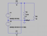
did more digging and for a cap of 10,000uf, esr of 0.04ohm and load of 10ohm, the initial in-rush current on the diode is a whopping 100amp! and can go as high as 40amp there after, about 10x the "average current" on the 10ohm load (the voltage is 36vac).
Wow!
Wow!
Your factor of 10x is also my experience, knowing that the rectifier diodes only conduct about 10% of the time, they have to furnish the energy for the other 90% as well. The exact value is probably not exact 10% because waveshapes vary and there are other variables, but for a ballpark figure its a good starting point.
Also, if you go to really large caps like 80.000uF or more, the only limit to the inrush current is the xformer's DC winding resistance and the wiring to the caps. Can you imagine how much energy is radiated into the amp from a wire carrying 100+ amps of current pulse? Scary, really.
Jan Didden
Also, if you go to really large caps like 80.000uF or more, the only limit to the inrush current is the xformer's DC winding resistance and the wiring to the caps. Can you imagine how much energy is radiated into the amp from a wire carrying 100+ amps of current pulse? Scary, really.
Jan Didden
millwood said:
I agree with the general view and think it is intuitive. However, I am not sure if the 85-90% figure is that accurate.
You would think that in a typical set-up, the RC constant for the whole amp is quite low: 3300uf x 10ohm =33ms. so I did a little simulation
here are some results:
1) for 1000ufx10ohm, the diode conducts about 50% per half cycle.
2) for 3300ufx10ohm, the diode conducts about 1/3 of the time.
3) for 10,000ufx10ohm, the diode conducts 1/4 - 1/5 of the time.
so 85% - 90% may be too aggressive of a figure for an average PS.
Would be interesting is one simulates ESR in the cap.
One very interesting I have found is that when the diodes are conducting, they don't conduct contineously. Rather, they go through conduct very briefly, then shut down, then conduct briefly again. This is more apparent when the RC constant is smaller.
the situation is likely worse if the PS is used to power an amp that is dirving audio signals into a speaker (the R).
To me, that means using small capacitors in a PS may cause excessive RF noise.
PS: I simulated the case where the capacitor has an esr of 0.1ohm, 1ohm to 10ohm (I have no ideal how realistic the values are). under all cases, the diode conducts at roughly the same time it would have conducted for a perfect cap (ESR=0).
However, with ESR, the conduct-shut down-conduct-shut down cycle mentioned above is gone.
With 0.1ohm and 1ohm ESR, the output voltage is about the same as those under the perfect cap. for 10ohm ESR, the output waveform is simply half wave. ie. the output voltage can never hold.
The above is done for C=10,000uf.
Millwood,
Didn't see this post before writing my above post.
This is interesting stuff you found. Indeed, it seems that my intuitive 85-90% is too pessimistic, but I think we agree on the principle.
The fact that you see that "now its on, now it isn't" in the conducting diodes might be a simulation artifact, especially since it disappeared with a little ESR. Spice is notoriously picky about ideal L's and C's or zero resistances, and I haven't ever seen it in reality. So, the fear that small caps cause excessive RF I think isn't warranted. I firmly belief that excessive LARGE caps can cause RF problems.
Jan Didden

planet10 said:
what this basically says is that the traditional 1.4 multiplier people use to convert secondary Vac to PS Vdc output is flawed when the PS is under load.
In this case, the PS output is considerably less. Just by eye-balling it, for a 36vac, 3300uf/10ohm system, a 20% discount off the peak ac voltage is about right. More so if the cap is smaller.
The other thing I think might be helpful is that if you are concerned about diode inrush current, using low ESR filter caps doesn't help.
Jonathan,jcarr said:My design partner, Petr Mares, was an engineer at the audio division of National Semiconductor. Succinctly stated, the Overture series was designed to be a high-performance amplifier that was targeted at mass-market commercial audio applications. Due to the mass-market target, the project goal was to offer high performance in an affordable monolithic solution (hybrid circuitry along the lines of National's LH-101 would offer better performance but at considerably higher cost), and make it as easy and trouble-free to use as possible.
If it is actually LH0101 you meant to say, do you know anything about the similar chips possibly in current production, by National or any other manufacturer? LH0101 seems to me extremely interesting but it is discontinued and it is impossible (for me at least) to come across it now.
Any input appreciated.
Thanks.
Pedja
Pedja:
>If it is actually LH0101 you meant to say<
Right you are. I hit the key next to "0" by mistake, which happened to be "-".
Elantec used to have a compatible device called the ELH0101, but I don't know what became of it after Elantec was acquired by Intersil.
Try these links, beginning with the proven Apex PA02.
http://eportal.apexmicrotech.com/mainsite/products/crossref.asp?guid=
http://eportal.apexmicrotech.com/mainsite/products/pages/op_amps/pa02.asp?guid=
No idea how good this is, but here's another device called the Satcon FLH0101.
http://www.satconelectronics.com/pages/32_linear_amplifiers.cfm
hth, jonathan carr
Thanks Jonathan.
I will look closer, but for now I do see the Apex uses similar topology. What I was interested for was actually most related to the fact the National’s LH0101 chip is current feedback amp. Unfortunately Apex’s chip datasheet isn’t quite clear about this and FMI doesn’t publish any schematic of interior circuit. Elantec’s chip seems like a full copy but I haven’t had success searching for Intersil’s ELH0101. Will check more, thanks again.
Pedja
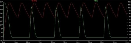
Noise generated by the caps
It is better to measure than to simulate, sure, but I don’t believe the truth is far from this.
Looks this way if 1000uF cap is used in a GC supply.
All else being equal but 10000uF is used.
What’s better? You bet. What’s the point? You know.
Pedja
It is better to measure than to simulate, sure, but I don’t believe the truth is far from this.
Looks this way if 1000uF cap is used in a GC supply.
An externally hosted image should be here but it was not working when we last tested it.
All else being equal but 10000uF is used.
An externally hosted image should be here but it was not working when we last tested it.
What’s better? You bet. What’s the point? You know.
Pedja
janneman said:I think we agree on the principle.
Absolutely. I think what you had proposed is very intuitive and interesting (I never thought about it before you raised it but it made a lot of sense to me).
janneman said:I firmly belief that excessive LARGE caps can cause RF problems.
Jan Didden
what mechanism would be at work here?
Re: Noise generated by the caps
that is consistent with my simulation as well. For 36vdc PS driving 10ohm loads, 10,000uf is about the minimum to maintain close to 36vdc throughout the cycles.
Pedja said:What’s better? You bet. What’s the point? You know.
Pedja
that is consistent with my simulation as well. For 36vdc PS driving 10ohm loads, 10,000uf is about the minimum to maintain close to 36vdc throughout the cycles.
other results
at 3300uf, voltage fluctuates from 28v to 35v;
at 6600uf, voltage fluctuates from 32v to 35v;
at 9900uf, voltage fluctuates from 32v to 35v.
so it seems that for this set-up (about 70wrms audio amp), 6600uf to 9900uf is about right. This kind of confirms the rule of thumb Sloan recommended in his book: 10,000uf for 100w rms output.
- Status
- Not open for further replies.
- Home
- Amplifiers
- Chip Amps
- Whats wrong with large filter caps for Gainclone?