Here are some measurements from Hobby Hifi magazine.
I can't understand the language, German?
Anyway, does this test explain the width of the baffle?
Judging From the graphs, it would seem that it's pretty wide because irregularities are occurring low in frequency.
But then again, the graph is a little small, hard to see.
Yes, it's German. The baffle is 17 cm wide with the driver (SEAS D2904/980000) centered. The given "%" values are the percentage of the radius from the baffle width.I can't understand the language, German?
Anyway, does this test explain the width of the baffle?
Last edited:
Oh, ok.
I looked at the graphs again.
I I misread them, I thought that 1000Hz was 100Hz.
Oops! 🙂
I looked at the graphs again.
I I misread them, I thought that 1000Hz was 100Hz.
Oops! 🙂
It may be of interest to remember the cabinets from the Good Dr. Earl are a bit larger than the max half cubic foot I build ( which is why I have not tried a pair of his, sure would love to). I found the difference quite dramatic. In case you missed it, a high quality painted finish is very hard and expensive.
I have an idea I may sketch up on how to do a low diffraction cabinet with two simple curved surfaces, so it would be possible to use a veneer finish.
I totally agree with the comments that the simple simulations and even simple measurements don't explain everything. They are only a starting point. They are a place to start "final voicing", which I do by listening. When Join Mitchel sounds natural, you got the mid-range balance right. What I can't explain, is what is making the nylon strings on Julian Bream's guitar sound metallic with some combination of less than perfect speaker and very wide bandwidth amps.
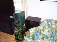
Attached is my best speaker to date sitting in front of one of my very stealthy subs. The speaker stand may be less that optimal, but has very high WAF.
I have an idea I may sketch up on how to do a low diffraction cabinet with two simple curved surfaces, so it would be possible to use a veneer finish.
I totally agree with the comments that the simple simulations and even simple measurements don't explain everything. They are only a starting point. They are a place to start "final voicing", which I do by listening. When Join Mitchel sounds natural, you got the mid-range balance right. What I can't explain, is what is making the nylon strings on Julian Bream's guitar sound metallic with some combination of less than perfect speaker and very wide bandwidth amps.
Attached is my best speaker to date sitting in front of one of my very stealthy subs. The speaker stand may be less that optimal, but has very high WAF.
Attachments
...and setting the tweeter offset,don´t make the reflections from the edges disappear.
Neither does adding a chamfer or roundover...
Every 3D object will diffract sound. Diffraction happens when the "space" into which a wave is propagating changes in "size". The amount of diffraction that will occur depends on the wavelength versus the size of the object and its facets/edges. The same phenomena happen whether you are talking about sound waves in air or ripples in water - the physics is the same. A smooth, spherical, or gently rounded edge still diffracts! It just does so gradually over a range of distances from the source so that the reflections do not add constructively or destructively at the listening position. You still get a transition, e.g. Olson and the point source on a sphere, but it is gradual with no oscillations (resulting from constructive and destructive interference).
What I often see cited as evidence that sharp edges are "bad" are studies of point source or nearly point source radiators (for instance a small tweeter) placed equidistant from 3 edges. For a rectangular box, this results in the absolute worst diffraction signature, and the only thing worse is when the source is centered on the end of a cylinder (and I have seen that, too). Under other real world conditions the result is much different (e.g. not as bad as it would seem). A 6" driver placed off center will have much smoother response because the size of the radiating surface and the distribution of pathlengths to diffraction points (e.g. from driver to edges) results in a wide distribution in the times that the diffracted sound reaches the listening position. This is not unlike what happens with a large roundover. With a small tweeter, the position and baffle size alone can be varied to give similarly smooth results.
This is pretty trivial to model on your computer using one of several tools. There is a great, free program called "The Edge" that assumes sharp edges. It is easy to play around with driver location and size as well as "microphone" position to see what is happening. Other excellent tools include the "Baffle Diffraction and Boundary Simulator" and the "Baffle Diffraction Simulator".
I typically use one of these to design the driver layout before cutting/routing the baffle. I also like to use drivers that have as large a diameter as is practical (dependent upon crossover frequency and beaming concerns) so that the radiating area is maximized. This also has other advantages, like reducing Xmax requirements, etc. and I believe that Earl Geddes also thinks along these lines.
Using off-center driver locations and as large a driver diameter as is practical, you can get great results with sharp edges without the hassle of chamfers or roundovers. Just don't locate your driver 4" down from the top edge, and centered L-to-R on your 8" wide baffle or you can expect a diffracted mess that no amount of crossover work can "fix".
-Charlie
I don't understand why it would be so difficult just to pass a chamfer or roundover over the edge, it could only help.
If its applying veneer that is the concern, you could just do the sides and keep the top and bottom flat, like this......

Ok, not the best example because of the curve, but a straight box....not so difficult.
It would actually be easier to veneer. Just wrap it around and put the seam in the back.
If its applying veneer that is the concern, you could just do the sides and keep the top and bottom flat, like this......
Ok, not the best example because of the curve, but a straight box....not so difficult.
It would actually be easier to veneer. Just wrap it around and put the seam in the back.
Last edited:
sweet paint job tvr.
These were just buffed out Krylon as they are basically prototypes. My last few were Dupont Centari and they were really sweet. The jobber is pushing Nason now. Just saw a notice. Dupont is selling out to the Carlyle Group. Wonder what that will bring.
I still have not fully solved the problem of seams and pinholes sinking in after a year. High build primer can make it look great when new, but a year later you see the edges. This is why correct concurs paint jobs take a year. They let it sink before a second fill and block. 4 day restorations on TV? What a joke. I don't have the patience to do that with speaker boxes.
I just use joint compound, then a few coats of wood glue on the outside...then sand.
But, yeah it's a pisser! The freggin paint takes longer than the build.
I've made a decision to just go with flat paint from now on.
But, yeah it's a pisser! The freggin paint takes longer than the build.
I've made a decision to just go with flat paint from now on.
Charlie ... you are correct in that diffraction still occurs. It is the smoothing of those diffraction peaks that are important. I'd guess that just repositioning a driver (asymmetrically) on a sharp edge baffle will only introduce 2-3 more sets of response "echos" off axis. Offsetting the driver is not a cure. Those posted graphs are just horizontal offset(s) ... imagine what the vertical looks like past another driver.
Last edited:
Offsets are indeed valuable- they spread the spectrum of the diffraction signature and lower amplitude accordingly.
Some of the most highly regarded, anechoically(true) designed loudspeakers in the world. Harbeth UK Roundover and offset? Hmm.. Makes you think..
Last edited:
I found a small explanation by Joseph D'Appolito. It's difficult to find information about how chamfering will affect this.
Talking sofar is about airborne wave diffraction from edges.
In addition to this, the edges of a panel can act as sound sources due to the panel self vibration. For this scenario, smoothing the edges is important.
George
Some of the most highly regarded, anechoically(true) designed loudspeakers in the world. Harbeth UK Roundover and offset? Hmm.. Makes you think..
Yup. Makes you think that they're ignoring a significant opportunity for improvement.
I've heard them and thought they were nothing special. What's your point?Some of the most highly regarded, anechoically(true) designed loudspeakers in the world. Harbeth UK Roundover and offset? Hmm.. Makes you think..
Ok, Acoustic benefits aside, if most if not all off the big boys are doing it, from a marketing standpoint, why would middle to lower end lines of speakers not do it?
How do they justify not doing it?
How do they justify not doing it?
I don't think that smoothing is a good word to use here. What happens is the wavefront is diffracted in such a way that the newly generated "echoes" (at edges, etc.) are spread out in time (which gives them different phase angles) such that they do not interfere (constructively or destructively) to any significant amount with the direct sound at the listening position. It's the interference with the direct sound that is causing the peaks and dips, the ripples, in the frequency response.Charlie ... you are correct in that diffraction still occurs. It is the smoothing of those diffraction peaks that are important.
I'd guess that just repositioning a driver (asymmetrically) on a sharp edge baffle will only introduce 2-3 more sets of response "echos" off axis. Offsetting the driver is not a cure. Those posted graphs are just horizontal offset(s) ... imagine what the vertical looks like past another driver.
As the wavefront encounters and then sweeps along and past the edge(s) it continuously diffracts. If you can make the "encounters" with the edge spread out in time (e.g. not the same distance from the source) as much as possible, then you have spread out the diffraction as well. Note that you can also tilt the baffle to do this for higher frequencies, because this will influence the distances between the source, diffracting edge, and the listening position.
So, with that said, there are not discrete sets of "response echoes" but rather a continuous distribution of them. The distribution can be stretched in several ways - by a large roundover, or by distributing in space the distances between the source and sharp edges. This applies equally to both the vertical and the horizontal axes, everywhere in front radiation hemisphere.
-Charlie
- Status
- Not open for further replies.
- Home
- Loudspeakers
- Multi-Way
- What's with the sharp edges on speaker boxes these days?