That's great, at least the main amplifier's good!
If you are using a PC's sound card as a source / pickup for the square wave, then probably it fails on both counts. You could generate a pretty clean square wave if you used a 555 IC instead, but it would still be a problem digitizing and displaying on a PC, since you'd need at least 100KHz (or better) BW to get a decent-looking waveform (and few sound cards can manage that)...
Unless you changed the volume control to some other value that is way lower than the original, it should be ok. So maybe there's more solder problems on the preamp?
BTW, if you do try the feedback capacitor - try something between 4.7 and 10pF. I got a bit cross-eyed last time - 47pF is about the right value if the FB resistor is 2.2K, not 22K as in your case...
Cheers!
I did change the pot, it was a 50K log, and I changed it to a 50K linear with a 11K resistor from wiper to ground to law fake it.
It's only distorting (oddly enough) on the right channel though, the left is not any worse than driving direct off the pc sound card (bypassing the preamp)....
It's possible there is a bad joint, I replaced some aging 10uF electros in the preamp, whilst I was doing the work on the power amp (ones I hadn't got around to doing when I did a cap changeout about 12 months ago), so I may have disturbed a nearby joint that may have been less than perfect.
I'll have a bit more of a dig around, I'm really thinking I'm going to have to get a scope and a signal generator though!!
Tony.
If I recall, there's a program or two you can download that will allow you to use your PC's sound card as a signal gen as well as an oscilloscope. Works of course only for AC-coupled line-level signals within the audio band, but hey, its free and it'll do the job you need!
Cheers!
Cheers!
Hi Clem_o,
yeah that's what I'm using 🙂 I use TrueRTA (the free version) for a Cro, it is helpfull up to a point. sine waves start to get very triangular looking above about 8Khz though (tis the sound card because it does it when looping back)...
I also use rmaa for doing my freq response, THD and IMD measurements.
I'm thinking seriously about getting one of these though http://www.bitscope.net/store/?p=view&i=product+BS310U
It is probably more than I need, but seems to be about the same price as a good second hand 100Mhz scope, or a new 40Mhz one (here in aus anyway). Has the disadvantage of needing to be hooked up to a pc to use, but has the advantage that screen captures are a breeze 🙂 I note it also says it has a built in signal generator, these guys are only about 20 min drive from my place might have to check it out.
Tony.
It's possible there is a bad joint,
I would give that a high probability since reflowing the solder joints helped the power amp section. I have learned to my own anguish that this can be much more common than I imagined even when the joints look perfect. Linsley Hood commented somewhere that a bad solder joiny behaves a bit like a diode though I would have thought it would be more like a low quality cap. This is where an oscilloscope can be handy. Sometimes if you have one of these diode- or cap- like joints you can input a sine and have it come out looking like it has passed through an integrator -- i.e., it looks a horizontal trace with spikes sticking up and down corresponding to peaks of the sine.
sam9: I can attest that its possible to have bad solder joints as well as old potentiometers act up with diode-like characteristics! Appears that whatever oxide layer builds up is partial to conducting in one direction (or, maybe its some kind of galvanic action), as I've heard and fixed problems like this in the past.
wintermute: go for it! Seems that particular product has got pretty nice specs. I got to use a Pico unit when I was in Australia some years ago, even got to do some programming to capture up the data. It didn't have a built-in signal generator nor logic level pickup though... I still find that having to lug a notebook around with it is a bit of a hassle though, and prefer using a standalone DSO (picked up a Tek TDS-210 in HK - price was really nice)...
Cheers!
One of the things I didn't mention was that after resoldering everything and doing a power up voltage check, I had 51V DC on the left channel speaker output  after doing a bit of looking around, determined the problem seemed to be with Q5.
with power off, I checked for shorts, I was getting 600mv voltage drop between collector and emitter (in diode test/continuity mode) I thought hmmmm that looks like a diode, reverse the probes and it was a much higher reading....
It turned out I had a VERY fine piece of wire much thinner than a hair, wich had found it's way onto the circuit board (probably when stripping a 512 strand wire) and was soldered to the emitter of Q5 the other end was just loosly touching the solder joint of the Collector (possibly with some flux in between. removed the culprit and surprise surprise no more 51V DC on the speaker output!!
So yeah I can attest to diode like properties of bad joints 😉 I had it happen yesterday!!!
Still undecided on what to do about a scope.... the bitscope is $660 Aus, and I really didn't want to spend that much (maybe up to $200)..... I think I'll wait for a while... It's just bugging me at the moment 🙂
I'm Really starting to wonder about my soldering skills too 😉 before the resolder the left channel had dc -6.5mv on the speaker output and the right had +5mv . After the resolder the left has +13.5mv and the right has +6mv.... I would have thought that they should be the same....
Tony.
after doing a bit of looking around, determined the problem seemed to be with Q5.with power off, I checked for shorts, I was getting 600mv voltage drop between collector and emitter (in diode test/continuity mode) I thought hmmmm that looks like a diode, reverse the probes and it was a much higher reading....
It turned out I had a VERY fine piece of wire much thinner than a hair, wich had found it's way onto the circuit board (probably when stripping a 512 strand wire) and was soldered to the emitter of Q5 the other end was just loosly touching the solder joint of the Collector (possibly with some flux in between. removed the culprit and surprise surprise no more 51V DC on the speaker output!!
So yeah I can attest to diode like properties of bad joints 😉 I had it happen yesterday!!!
Still undecided on what to do about a scope.... the bitscope is $660 Aus, and I really didn't want to spend that much (maybe up to $200)..... I think I'll wait for a while... It's just bugging me at the moment 🙂
I'm Really starting to wonder about my soldering skills too 😉 before the resolder the left channel had dc -6.5mv on the speaker output and the right had +5mv . After the resolder the left has +13.5mv and the right has +6mv.... I would have thought that they should be the same....
Tony.
Forgot about the GST, sure has a way of popping up the price!
Regarding the offset voltage - don't worry about it. Its pretty normal that the left and right offsets aren't quite the same. Gain variations in transistors are pretty big unless you take the time and effort to match them out!
You may want to check the offset voltages again after 'some time of use' - you'll probably see a tempco at the very least... as long as the voltage reads just a few tens of mV I'm sure your loudspeaker won't mind...
Cheers!
Thanks Clem_o,
I did try to match the transistors (not mosfets) both in pairs and across channels, though I think I did end up with a slight difference in hfe between left and right for q4 and q5.
edit: bit about preamp deleted.... was the sound card preamp clipping not the amp... changed it to .1X and no clipping evident... 🙄
Tony.
OK this looks more like the problem 🙂 I had figured that I was getting intermodulation distortion, based on listening and only noticing the distortion in the tweeter, when there were loud bass passages.
Now to track it down!! I'll have to solder my test leads in before the final opamp to see if that's where it is occuring.
Tony.
Now to track it down!! I'll have to solder my test leads in before the final opamp to see if that's where it is occuring.
Tony.
Attachments

Hmmm interesting graphs. Is that the preamp output with or without any loading? Look for leaky decoupling capacitors (and yes, bad solder joints... ! )
Cheers
Cheers
Hi wintermute,
I have a 16bit Serial port Oscilloscope and FFT analyser I'm about to flog on eBay. It's 100KHz sampling and 84 dB resolution. 2 channel CRO 1 button CRO/FFT. If you're interested.
I'm looking for a$100.
Cheers,
Greg
I have a 16bit Serial port Oscilloscope and FFT analyser I'm about to flog on eBay. It's 100KHz sampling and 84 dB resolution. 2 channel CRO 1 button CRO/FFT. If you're interested.
I'm looking for a$100.
Cheers,
Greg
clem_o said:Hmmm interesting graphs. Is that the preamp output with or without any loading? Look for leaky decoupling capacitors (and yes, bad solder joints... ! )
Cheers
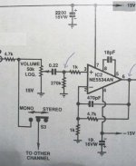
That was with the preamp still connected to the amp. might try unloaded.... I have attached the schematic of the offending bit in the preamp... rmaa measurements taken at the points with arrows. before the ne5534 the IMD is actually higher (probably due to having to crank up the sound card input levels to get enough signal) for the left channel, but it is relatively consistent between channels, so I guess it is something with the opamp part of the circuit, at least I have somewhere to look 🙂 the whole preamp is an abomination of cmos switching ic's and lf351 buffers! The output of the opamp is directly connected to the 1uf coupling caps of the amp.... it used to go to another ne5534 in the tone controls, and then a balance pot but I bypassed these years ago.
amplifierguru said:Hi wintermute,
I have a 16bit Serial port Oscilloscope and FFT analyser I'm about to flog on eBay. It's 100KHz sampling and 84 dB resolution. 2 channel CRO 1 button CRO/FFT. If you're interested.
I'm looking for a$100.
Cheers,
Greg
Thanks for the offer Greg, 100Khz is definitely better than what I have, but I was thinking I should aim for something in the Mhz range.... I think if I was going to spend $100, I'd get the DSE 1 channel 10Mhz scope for $158 🙂
I think I'm going to have to sign off now, as the gf is coming for dinner 🙂
Tony.
Attachments
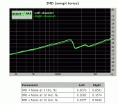
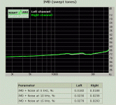
OK that previous graph is rubbish 😉 definitely not a good idea to crank up the gain on the sound card, tried using the 10X gain on the SC preamp instead and have a much better result 🙂 definitely shows that the problem is occuring between the input to the ne5534 and the output!!
Tony.
Tony.
Attachments
I'm Really starting to wonder about my soldering skills
I found 2% silver solder helped. Not because of any magic sonic properties but just due to the slightly lower melting point.
OK that previous graph is rubbish definitely not a good idea to crank up the gain on the sound card,
Yup. I spent a week in the spring trying to figure out whay an amp that sounded OK had such terrible RMAA distortion figures. What I was seeing was distortion from an overdriven sound card.
Hi sam9,
Don't you mean higher melting point? That might help the solder wet. I find using solder flux really helps, clean the board with lacquer thinners and a toothbrush when you are done. Then inspect the connections.
-Chris
Don't you mean higher melting point? That might help the solder wet. I find using solder flux really helps, clean the board with lacquer thinners and a toothbrush when you are done. Then inspect the connections.
-Chris
clean the board with lacquer thinners and a toothbrush when you are done. Then inspect the connections.
this is how i do it...denatured alcohol will also give good results...an inch or so toothbrush with shortened bristlles for large areas are better, then toothbrush to clean residues...
Yeah it seems like a good idea to clean up the board too, perhaps some wierd coupling issues causing the intermod to rise... Looking at the values around the 5534, gee that's a *really* slowed-down circuit!! Try looking at the 18pF cap and see if there's too much solder flux under it (at the same time I'd probably drop that value to maybe 3.3 or 4.7pF, and the FB network (4.7K w 1K to ground; 470pF) - you may want to try changing that, in case its presenting too much of a load to the 5534 - a 47pF instead would probably a better choice...
- Status
- Not open for further replies.
- Home
- Amplifiers
- Solid State
- what's going on here?? (much head banging)