Yes- it is similar to the original Cecil Hall patent of the original Circlotron. It included a driver tube integrated into the output section power supplies.That looks interesting. Does it work - has it been built?
I located an extremely useful tool for creating SPICE models for tubes. If you can locate the curves in any graphic format it allows you to create a model simply by using sliders to fit the curves.
Model Paint Tools: Trace Tube Parameters over Plate Curves, Interactively
This is perfect for creating a model for the 6H13C (using a 6AS7G now) and also for creating a family of models all for the same tube but that differ randomly in their characteristics like real tubes.
I've tried it and it works, although some of the features aren't quite as described. There is one java applet for triodes and one for pentodes. Talk about making life easier for modeling unusual tubes, especially those Russian tubes that are hard to find models for.
Don't give him any more ideas, Banat. Give him drill bits and a soldering iron. we're all waiting the REAL results!😀
No need for concern. I have my drill, my hole saws, my bits, my soldering station, sixty 6H13C tubes, plenty of 6SN7s, 1/8" aluminum sheets for the chassis tops and bottoms, power trannys, octal sockets, etc. etc.
I'm done modeling OTLs to decide which one to build. It's now a matter of fine tuning the circuit I have and making time to build it. I'm just finishing up setting up my new "lab" where I'll be constructing all my future projects. This will be the first OTL and is next in line before any other builds. It will take some time as I've got a lot on my plate right now, but the parts have just about all been acquired and I'm almost ready to drill.
Right!
"A cartridge is a loudspeaker in reverse so if it is a good idea to be balanced for a loudspeaker why not do the same for the cartridge?"
So can someone help me and point me in the direction of decent fully balanced phono stage / preamp circuits?
This seems to me to be a subject for another thread. If you start one, I will be happy to participate.
Don't give him any more ideas, Banat. Give him drill bits and a soldering iron. we're all waiting the REAL results!😀
The REAL good results allready exist, for thirty years or more backward from today.😉 And thats the (Ralph-s)Atmasphere OTL Circoltron power amps.🙂 for sure.
Now, who want to made tube DIY OTL Amps with real good sonics ,first step is drill bits,than soldering iron,than......, good music 😀
Best Regards Man

This seems to me to be a subject for another thread. If you start one, I will be happy to participate.
Done!
The REAL good results allready exist, for thirty years or more backward from today.😉 And thats the (Ralph-s)Atmasphere OTL Circoltron power amps.🙂 for sure.
Now, who want to made tube DIY OTL Amps with real good sonics ,first step is drill bits,than soldering iron,than......, good music 😀
Best Regards Man
The amps are SLOWLY coming together. I've just got my new "lab" set up and my tools moved into my new house, so I should be getting busy on these very soon.
I've started breaking in the tubes, both 6C33C and 6H13C for the two OTLs on a rig I slapped together to measure the plate curves and try to at least eliminate tubes that are way out of spec with the others, with the heaters on and all pins tied to one side of the filaments. How long am I supposed to let these break in? I assume I'm gettering the gas that either entered the tube or outgassed from the internal parts?
An externally hosted image should be here but it was not working when we last tested it.
with the heaters on and all pins tied to one side of the filaments. How long am I supposed to let these break in? I assume I'm gettering the gas that either entered the tube or outgassed from the internal parts?
72 hours should be sufficient. Anytime you get a new tube whether you use it or not, this should be done. As far as we can figure, you are curing the cathode coating.
The amps are SLOWLY coming together. I've just got my new "lab" set up and my tools moved into my new house, so I should be getting busy on these very soon.
I've started breaking in the tubes, both 6C33C and 6H13C for the two OTLs on a rig I slapped together to measure the plate curves and try to at least eliminate tubes that are way out of spec with the others, with the heaters on and all pins tied to one side of the filaments. How long am I supposed to let these break in? I assume I'm gettering the gas that either entered the tube or outgassed from the internal parts?
An externally hosted image should be here but it was not working when we last tested it.
Awakening(precondition) process is for long standing unused tubes the very good start point for sure.(on the each 6c33c-b tube is engraved production year,just near on the right side next the factory logo(Ulyanovsk),74 mean year 1974 or 82 mean 1982..., so looking in average years this tubes is the real NOS ! and they need careful kathodes precondition for normal operation.
So 72 hours of kathode precondition per each tube, done exactly in that way which you already doing,with all pins tied together on the one side of the filament.
Be sure that this `break in` process is related with kathodes precondition but not to much with internal tube gas,this tubes are very good sealed so the tube vacum loses is very rare,except if some glass crack exist usually near to the tube pins, but this is very rare effect indeed for Russian high MIL production norm.
There is something else related to 6c33c-b/6h13c tube precondition:Since the internal tube metal structure is produced & formed from magnetic materials,precondition of this tubes with 72 hours filaments turned on mean internal demagnetization of the tubes too,with relative high standing temperature radiated from glowing kathode to surrounding metal structure of this electron tubes,actually this demagnetization process can not be done in five minutes but in 72 hours is done for sure.
To not forget:After the 6c33c-b precondition process use some very fine sandpaper and clean each tube pins,that well remove the oxidation layer from this really underdimensioned tiny tube pins,and check each tube ceramic socket contacts force and contacts surface condition.
Best Regards
Last edited:
Awakening(precondition) process is for long standing unused tubes the very good start point for sure.(on the each 6c33c-b tube is engraved production year,just near on the right side next the factory logo(Ulyanovsk),74 mean year 1974 or 82 mean 1982..., so looking in average years this tubes is the real NOS ! and they need careful kathodes precondition for normal operation.
So 72 hours of kathode precondition per each tube, done exactly in that way which you already doing,with all pins tied together on the one side of the filament.
Be sure that this `break in` process is related with kathodes precondition but not to much with internal tube gas,this tubes are very good sealed so the tube vacum loses is very rare,except if some glass crack exist usually near to the tube pins, but this is very rare effect indeed for Russian high MIL production norm.
There is something else related to 6c33c-b/6h13c tube precondition:Since the internal tube metal structure is produced & formed from magnetic materials,precondition of this tubes with 72 hours filaments turned on mean internal demagnetization of the tubes too,with relative high standing temperature radiated from glowing kathode to surrounding metal structure of this electron tubes,actually this demagnetization process can not be done in five minutes but in 72 hours is done for sure.
To not forget:After the 6c33c-b precondition process use some very fine sandpaper and clean each tube pins,that well remove the oxidation layer from this really underdimensioned tiny tube pins,and check each tube ceramic socket contacts force and contacts surface condition.
Best Regards
Awakening! I like that term. Thanks for all the useful information.
I have two types of 6C33C. Some are old, like the early 1970's, with the year engraved to the right of the logo. But some look newer with the date code to the left of a different logo, and these are all from the mid to late 80s. The old ones have a lower pitch when you tap on them indicating to me that they are made of heavier glass. Otherwise all of them are BEAUTIFUL tubes! I mean these look first rate quality. I had one that came cracked. If there's a gas leak it's obvious. The silver getter turns clear, almost invisible when air gets in.
I agree these contacts are insanely small! 😱 The heaters need over 3 amps but the pins are like the pins from miniature tubes.
I also found out that the gold plated Chinese sockets I bought are junk. They LOOK nice, but the looks decieve. I thought one of the tubes had a broken heater on one side and started cursing the Russians, then I jiggled the tube, the heater came on and I started cursing the Chinese. Now after thinking about it I'm cursing myself (the Americans) for being dumb enough to not listen to the warings about Chinese sockets.
I came up with a thought on this. Has anyone tried wire-wrap to connect the pins on a 6C33C? It seems to me like a homemade tube holder could be easily made and the pins attached using a wire wrap tool and the right kind of wire. I suppose the thermal cycling would eventually loosen the contact, but I wouldn't want to suppose it wouldn't last a long time without trying it first. I disassembled a few TVs from the 50s or 60s that used wire wrap in all tube equipment. It seemed to work fine although they used tube sockets of course. But I see no reason you couldn't wrap directly around the pin of a tube.
Certainly the actual area of contact between the wires and the pins would be HUNDREDS of times the area of contact of these crummy socket contacts.

On one last note, I attempted to solder the pins on the cracked tube with nothing to lose. It wouldn't stick with the iron on the highest setting. If I had a more powerful iron perhaps...but the solder would melt under heavy operation (over 300C I think).
How about WELDING to the pins!!!??? That would make a fine connection!
Last edited:
Awakening! I like that term. Thanks for all the useful information.
I have two types of 6C33C. Some are old, like the early 1970's, with the year engraved to the right of the logo. But some look newer with the date code to the left of a different logo, and these are all from the mid to late 80s. The old ones have a lower pitch when you tap on them indicating to me that they are made of heavier glass. Otherwise all of them are BEAUTIFUL tubes! I mean these look first rate quality. I had one that came cracked. If there's a gas leak it's obvious. The silver getter turns clear, almost invisible when air gets in.
I agree these contacts are insanely small! 😱 The heaters need over 3 amps but the pins are like the pins from miniature tubes.
I also found out that the gold plated Chinese sockets I bought are junk. They LOOK nice, but the looks decieve. I thought one of the tubes had a broken heater on one side and started cursing the Russians, then I jiggled the tube, the heater came on and I started cursing the Chinese. Now after thinking about it I'm cursing myself (the Americans) for being dumb enough to not listen to the warings about Chinese sockets.
I came up with a thought on this. Has anyone tried wire-wrap to connect the pins on a 6C33C? It seems to me like a homemade tube holder could be easily made and the pins attached using a wire wrap tool and the right kind of wire. I suppose the thermal cycling would eventually loosen the contact, but I wouldn't want to suppose it wouldn't last a long time without trying it first. I disassembled a few TVs from the 50s or 60s that used wire wrap in all tube equipment. It seemed to work fine although they used tube sockets of course. But I see no reason you couldn't wrap directly around the pin of a tube.
Certainly the actual area of contact between the wires and the pins would be HUNDREDS of times the area of contact of these crummy socket contacts.
On one last note, I attempted to solder the pins on the cracked tube with nothing to lose. It wouldn't stick with the iron on the highest setting. If I had a more powerful iron perhaps...but the solder would melt under heavy operation (over 300C I think).
How about WELDING to the pins!!!??? That would make a fine connection!
Generaly:when Air get inside the tubes(due glass crack) than silver shiny barium getter becomes milky white colored,but when the shiny barium getter it becomes almost invisible or almost transparent thats the sign of 6c33c tube life end(due evaporated gases released from tube metal structure),here is exception since exist some very rare 6c33c-b(Svetlana electron tube factory-St.Petrsburg/Leningrad) tube version with circonium getter ,and this tubes is with completely transparent glass.
Yes the 6c33c-b tube pins is insanely small and short,everything which can be done is to chose the right tube socket brand.
Chinese tube socket is Fake and Bad!,but must say that gold plated tube socket is not good for 6c33c-b tube whatever socket brand it is,silver plated tube socket contacts is the best solution for 6c33c-b.
To try to made some custom pins contacts with wrap some copper wire around the pins is BAD idea,since the tube pins need to be mechanically free not mechanically rigid,and this is due tube thermal dilatation.(special pointed this for extreme hot running 6c33c-b tube !).BTW it is not impossible to made tube socket contacts in that way, but than you need special silver coated brass or bronze wire and lot of very precision mechanical work and skill !,final good results is Not guaranteed anyway.
To solder or weld the 6c33c tube pins-NO WAY!-thats `operation` will Destroy the tube instantly .
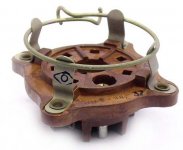
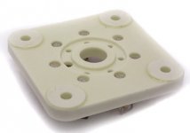
Here is some picture and useful link for you,picture is related to two original Russian 6c33c-b socket,first is normal ceramic socket(not bad) and second is original brown tube socket with integrated tube holder,this brown one is better one and cheaper to(9$),both socket type is available from- RU Tubes.com-
Second link is from JacMusic.com and have some very useful information related to 6c33c socket contacts wiring method.
-Since this great DIY forum thread is primarly dedicated for Atmasphere M60 OTL Circlotron Amps, for further necesary information please contact me on PM,(just i will not to abuse this great thread with 6c33c stuff anymore!)-.
BTW,what`s up with PSpice simulation for two 6sn7 driving directly coupled to 16x 6h13c Circlotron, conected in double `tube Darlington `configuration?Tube sockets - Vacuum radio tubes, capacitors, socket for tubes, nixie, ferrites from military Russia. Datasheets tubes and help. Worldwide shipping
Yamamoto Soundcraft / Teflon Sockets and parts
Best Regards 🙂
Attachments
Last edited:
BTW,what`s up with PSpice simulation for two 6sn7 driving directly coupled to 16x 6h13c Circlotron, conected in double `tube Darlington `configuration?
Best Regards 🙂
Those are in parallel. It looks deceiving, but the grids attach to the grids, cathodes to cathodes, etc.
Thanks for the socket info. The contacts on the Chinese sockets don't even line up with the pins on the tubes. They got it close, but far enough off that it doesn't make very good contact.
Which Chinese tube sockets are you talking about? The Yamamoto? The other Teflon, or some other sockets? What source?
Stuart
Stuart
Those are in parallel. It looks deceiving, but the grids attach to the grids, cathodes to cathodes, etc.
Think you are not understand me correct:
` Double Tube Darlington` junction is formed with each separate driver tube anode conected to output power tube anode via 100 ohm resistor (instead direct to separate+300V source), for each of two independent phase of Circlotron output power stage in the same way.
Best Regards
I avoided this technique as I was concerned about modulation on the plate of the driver tubes. Additionally I found that they were 'starving' with the result of additional distortion unless the plate voltage was high enough. The driver must be able to swing more voltage than the voltage amplifier can feed it, without saturation.
I value my loudspeakers.
I don't know about you but I don't want to loose my loudspeakers to melted voice coils. The only thing protecting loudspeakers in a transformerless OTL amp is maybe a 50 cent fuse or a electrolytic or non polar capacitor according to my reading. The same is true of a complementary symmetry BJT transistor amp. Only a 50 cent fuse and a feeble npn and pnp junction that can melt in a nanosecond. Only a 50 cent fuse standing between your speakers that you may have spent alot on money for and enough stored joule capacitance energy to lift a 9 pound dog, 3 feet into the air. I'll take a good output transformer any day. Ray
I don't know about you but I don't want to loose my loudspeakers to melted voice coils. The only thing protecting loudspeakers in a transformerless OTL amp is maybe a 50 cent fuse or a electrolytic or non polar capacitor according to my reading. The same is true of a complementary symmetry BJT transistor amp. Only a 50 cent fuse and a feeble npn and pnp junction that can melt in a nanosecond. Only a 50 cent fuse standing between your speakers that you may have spent alot on money for and enough stored joule capacitance energy to lift a 9 pound dog, 3 feet into the air. I'll take a good output transformer any day. Ray
I avoided this technique as I was concerned about modulation on the plate of the driver tubes. Additionally I found that they were 'starving' with the result of additional distortion unless the plate voltage was high enough. The driver must be able to swing more voltage than the voltage amplifier can feed it, without saturation.
Yes,agree with you about this CF driver stage `distortion & starving`behaviour (effect) when CF driver tubes 6sn7 is connected in this `Double Darlington `driver topology.(BTW- I was just curious to see Sampleacurates PSpice graphicon demonstration.)
Since I use miniature CF drivers triode tube 6c45p with different B- supply value, to drive directly each 6c33c power tube ,connected in Multiphase OTL Circlotron topology(four phase),there this `Darlington`conected CF drivers works just fine,but that Amps topology is different from your M60 OTL Circlotron Amp topology anyway.
Best Regards
Now I understand - I never did model it and now that the truth is exposed probably won't be 😉
I'm still tweaking a Broskie autobias circuit and burning in my 6C33Cs and 6H13Cs.
BTW, the sockets are Chinese origin, ceramic with gold plated fork type connectors from ebay, that's all I know. Junk. Also the shiny coating was on all my 6C33C tube pins per the article you linked to - had to knock it off with sandpaper. Thanks.
I don't know about you but I don't want to loose my loudspeakers to melted voice coils. The only thing protecting loudspeakers in a transformerless OTL amp is maybe a 50 cent fuse or a electrolytic or non polar capacitor according to my reading. The same is true of a complementary symmetry BJT transistor amp. Only a 50 cent fuse and a feeble npn and pnp junction that can melt in a nanosecond. Only a 50 cent fuse standing between your speakers that you may have spent alot on money for and enough stored joule capacitance energy to lift a 9 pound dog, 3 feet into the air. I'll take a good output transformer any day. Ray
I've been doing this for over 34 years; your fears are groundless. I too was concerned in the old days and some of my early amplifiers had as many as 9 fuses. I found in the process that the excess fuses were causing more troubles rather than less. Ultimately I settled on a system of 3 fuses, one in particular which controls the B+ for the output tubes.
Its been very effective- to date I cannot find a legitimate example of a speaker damaged. There are a few cases that are *not* legitimate (and even the those can be counted on your hands with fingers left over):
* incorrect power tubes installed!
(which is the sort of thing that can take out an OPT BTW...),
* over-rated fuses installed!
(which is also the sort of thing that can take out an OPT BTW...)
It helps to understand how the amplifier works. Once that is known, it is easy to see how a simple fuse can be very effective.
- Home
- Amplifiers
- Tubes / Valves
- What tubes for a OTL tube amp?