6AS7G is better for AB2 (dissipates more heat when grid current happen)
I follow to make the same in few months. I will be watching this thread. I lost but I rediscover today, just when I starting with SS amps.
I follow to make the same in few months. I will be watching this thread. I lost but I rediscover today, just when I starting with SS amps.
The 6AS7G is preferred as it handles grid current better than its GA version and the 6080 variants. The thing to look for is the size of the grid heatsink- the small ones can warp and arc if you operate the tube in the grid current region.1. Besides being in current production, is there any reason to prefer 6AS7G over NOS 6AS7GA/6080/WA/WB/WC variants? <snip>
I think you will find that the complexities of a direct coupled circuit with DC servo will what makes the amp impractical. For one thing, you want the timing constants in the power supply to be lower than that of the amp and if its DC coupled, that's pretty hard to do. The result can be LF instability. However, if you have success I am sure many here would love to see what you come up with.
Hi everyone,
I just finished breadboarding one channel of this design and it sounds very promising.
I deviated slightly in that I'm only using 300uF total in the pre/driver PS stages, and only 2000uF per bridge in each phase of the output. Completely hum free on my 87db test speakers despite it. I will add more later to subjectively compare.
I'm using series filaments (one 28.6v transformer for each set of 4 tubes) on each phase of the output section.
I'm using two 120v:12v transformer to derive two 12v series heater strings for the preamp/driver. Then its going through a second 120v:12v in reverse to get back to 120v nominal, then a voltage doubler supply boosts me to about 400v total. This is obviously not enough - I get some weird square wave type of distortion due to real bad bias points. I have a proper 230v transformer on order that will address this. Output bias circuit has been temporarily adjusted because it woudl have been way too hot because of the -200v supply vs. designed -300v.
I'm also using 6FQ7 tubes instead of 6SN7.
No critical listening yet, but it does work. The dynamics seem scary good despite the extremely sub-par bipolar PS voltages. Can't wait to finish sorting this one out and start on the second channel.
My total cost has been about $300. I've been buying transformers, tubes, etc. over the past 10 years knowing I would eventually build this, and the time has finally come. I actually bought JAN Sylvania 6080WCs about 14 years ago when they were about $2-3 each.
So I sorted out my front end power supply a few weeks ago. The weird distortion ended up being a bad source.
In a nutshell...everyone needs to build these. Even despite my changes that i'm sure compromise the original design these sound ridiculously good. Here's my setup...
Rasperry pi->M-audio Sonica 24/96->m60 clones->klipsch r15m
In a 10x10 room this system has no problems getting crazy loud but it always stays clean. These speakers are rated 94db but I suspect that figure is inflated somewhat like other klipsch consumer grade stuff. The system simply never runs out of steam though. I swapped in my ST70 w/ beefed power supply, Amperex tubes, etc. and it was simply no contest at any volume level but especially higher volumes.
tossing CSN, Genesis, Steely Dan, Wings, Supertramp at these they simply sound great most of time but they are kind of ruthless. some of the csn stuff on deja vu isn't recorded too well, and these don't sugar coat that fact. this could be more of my parts/design deviations though. I've always thought the 6cg7 sounded brighter than the 6sn7 as a generality. i've done a little tube swapping with the cathode follower and middle tube of the gain stage but haven't drawn any conclusions yet. this amp seems rather insensitive to the tubes afaik and i have a pretty big selection of matching 6cg7s to work from.
I've switched the ST70 back in and out twice now, and now its sitting in a corner in the basement.
There speakers have cheap first order crossovers w/ no zobel, baffle step, etc. The bass sounds fine to me with everything i've tossed at them so far. Tight, clear, and well-defined. I've always bought into the low Z arguments but started questioning it when I played with SETs a while back. Now I'm convinced its all meaningless, at least up to the point where the amp matches the speaker. too many other variables obviously.
So whats the next step? I need to get proper chassis built. these are currenty sitting on a two 24"x8x" boards with sheet metal screwed to one side to hold all the tube sockets.
I'll eventually put these head to head with the rest of my system - several other amps like a HK Citation V, Heathkit EA2 and 3 monos,and my 2a3 LW. And the jbl 2226/emilar/renkus horn setup. I have a feeling these might be my best amps to date.
i haven't done any measurements but the power is definitely a tad higher than my st70. its hard to tell because that falls apart at volumes where these seem to keep it together. i suspect i'm not even be driving these to full power with the m-audio dac. i'll get around to measuring soon. i have scoped things and have just a tad of residual buzz in the tweeters when i'm up against the speakers but I'm pretty sure a lot of that is the bird nest layout, no isolation, and transformers pointing the "wrong way" i have going on with the breadboards right now.
I'm running my bias where I measure 500mv through each 1R resistor in the power supply so 62.5ma I guess. plate voltage is always rock steady @ 140v. We'll have to see how these do long term for reliability but I have 6-8 6080 tubes left in my stash so I should be set barring no serious disasters. that remind me i need to add fuses too. 🙂
thank you again ralph for sharing your design with the diy community. that was a seriously cool move. haters need to build and listen. i did the technics futterman variant w/ 8 6as7/channel years ago. it never made it past 3-4 auditions on the breadboards, with essentially the same exact parts i'm using now. never bother trying rosenblitz because it looked too similar to me. yeah i should maybe give that a chance. but this is something else vs. the futterman.
Anyone else built these?
Last edited:
Nope not yet, still collecting parts, which driver circuit are you using? Why the 6cg7 choice?
Laters
Drew.
Laters
Drew.
I'm running ralphs driver circuit verbatim as published by him in this thread, just with 6cg7 instead of 6sn7 because i had about 30 of them on hand. They are equivalent or close at least. I'm using the 100k plate resistors per his schematic and not ths 50k variant published a little later in someone elses revision but i'll try that eventually too. Oh and i added a 10k bias adjust pot below the 5k balance one so i could adjust bias voltage. i can now adjust between about 40ma to 70ma per section Avg. I keep it around 60 So far.
Last edited:
Sweet- good work!
When doing a metal chassis- some tips (all about proper grounding and AC wiring):
1) ground the chassis to the ground connection of the power cord.
2) run a star grounding scheme in the amp circuit, but do not allow the amplifier to be at chassis ground at any point.
3) run a 100 ohm resistor to chassis from the central ground point. You may bypass it with a pair of rectifiers wired in parallel but backwards with respect to each other.
In this way the chassis can shield the amp, but ground loops will not occur. If there is a problem, the rectifiers will prevent the 100 ohm resistor from getting fried.
4) Run the hot side of the line to the fuse first thing. From there to the power switch and then the rest of the circuit. That way if the switch is ever shorted to chassis the fuse can blow.
jdarg, I recently finished one a few months ago. I posted about it on the Photo Gallery topic starting at post http://www.diyaudio.com/forums/tubes-valves/71300-photo-gallery-645.html#post4143764 in case you hadn't seen it. It's actually two M-60s on a common chassis.
Like you, I'm using 6CG7s instead of 6SN7s, but only for the cascode's common-grid stage and the cathode followers. I thought I could get more gain by using a higher gm triode for the cascode input stage and ended up using 6BQ7s since I had a bunch lying around. Simulations didn't show a whole lot of difference vis a vis distortion, but it allowed me to use lower values for the plate load resistors. The neat thing about using the differential cascode driven by a constant current source is that many different types of tubes can be substituted in the cascode input stage without upsetting the dc operating point significantly. There's a whole universe of 9A-base dual triodes out there to try out.
My version is dc coupled from input to output. I eliminated the coupling capacitor between the cascode plate and the cathode follower grid and replaced it with a resistor. The cathode follower grids have constant current sources connected to B- so that the voltage drop across the resistor is constant and the cathode follower grids and output triode grids have the correct bias voltage. The CCS uses a 12AX7 with the grids cross coupled to the opposite cathode. It's a bit hard to explain in words, so I guess I should post a schematic later.
I am using the amplifier with no negative feedback loop and it sounds great. No problems with hum or buzz at all. It sounds great at low levels because of the low noise, and it sounds effortless up to the point where the speakers cone excursion becomes excessive. (My speakers are MarkAudio A10P Pensils, and my sources are optical DACs driven from a CuBox i4 running GeeXbox, or my PC running Foobar 2000. All my music is FLAC ripped from CDs.)
I've got a few tweaks I'm going to add in the coming weeks, one is a dc servo to automatically zero out the dc offset at the output. My dc coupling mod probably makes dc stability more of an issue in my amp, so you probably won't have any problem if you go ac coupled. I tweaked the amp's balance pot after about 2 hours of run time for zero volts, but for the first twenty minutes or so the offset is fairly high, around 900mV, before it settles in. It's not sonically obvious, but I don't want it there. Also, it doesn't always settle in the same way each time I run it, probably because the tubes are aging differently. I'll keep you posted on my progress.
Sorry for the long post, but there are so many really things to say about the M60's cool and innovative design that it's hard to stay focused on just one. Build one, you'll love it.
Schematic and DC coupled= Heck yes please!
Have a suggestion for you onve I see it, need to refresh my head a little......
Fantastic stuff, looking forward to getting these running g!
Laters,
Drew.
Have a suggestion for you onve I see it, need to refresh my head a little......
Fantastic stuff, looking forward to getting these running g!
Laters,
Drew.
This is a screen capture of the driver part of the dc-coupled OTL schematic. I hope it's clear.
A few notes: The resistor values were selected to make use of my stash of RN60 metal film resistors, so if the values look funky, that's why. You'll see that I series-paralleled resistors in a few locations for voltage and power de-rating purposes, instead of buying new high-wattage resistors. Also, the feedback resistors are shown disconnected from the output rails.
The nets labeled BIAS-A and BIAS-B are for future connection to the dc balancing servo (not shown yet until I prove it to work).
Attachments
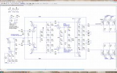
Oh, R58 and R59, the dc balance pot, are unmatched here because I was testing the servo loop's range. I should have edited the values back to nominal 5k and 5k.
Another note: Lots of resistor values in the posted schematic are specific to the power supply rails I used for my specific version of this amplifier; these were dependent on the transformers I had available so don't treat them as gospel. When you implement/simulate your own design, these will very definitely need to change. Also, as noted previously, I limited the resistor values used in my implementation to those I had in my personal stockpile, not the entire gamut of E96 values available.
Another note: Lots of resistor values in the posted schematic are specific to the power supply rails I used for my specific version of this amplifier; these were dependent on the transformers I had available so don't treat them as gospel. When you implement/simulate your own design, these will very definitely need to change. Also, as noted previously, I limited the resistor values used in my implementation to those I had in my personal stockpile, not the entire gamut of E96 values available.
I attempted to do a rigorous analysis of the CCS last year, and was partially successful...to the best of my limited ability, the impedance of the CCS is roughly mu*Rk, within a factor of 2. It's been a long, long time since I did circuit analysis in university and my "skilz" have blunted with the passage of time (ah, well...)
A heuristic, or less charitably a hand-waving, "truthy" explanation, of how the CCS works goes as follows:
When the signal at U3-P increases by dV, the signal at U4-P decreases by the same amount (in the linear region of operation), and the current in U8 would increase (U9 decrease) accordingly.
The voltage at the cathodes of U8/U9 also increase/decrease, but since the grids of U8/U9 are cross-connected to the cathodes of U9/U8, the grid to cathode voltages will decrease/increase, causing the plate currents in U8/U9 will be forced to decrease/increase, thereby maintaining constant plate current, and hence constant voltage drop across R50/R57.
Caveat: This behavior only holds true at dc AND if the plate voltage swings at U3/U4 are equal and opposite. At high frequencies, due to parasitic and inter-electrode capacitances and stray inductance, this condition will not be met. At high ac voltage swings, the balance requirement will not be satisfied.
I've found by simulation and measurement that the CCS operates satisfactorily up to at least 50 kHz and up to amplitudes where the output tube nonlinearities (especially when driven towards cutoff) swamp the driver "non-ideality".
If you simulate the circuit, you'll want to monitor the voltage drop across R50 and R57 and the currents in those branches at full signal power. I was satisfied that the CCS compliance was good enough to maintain essentially no ac signal loss from the cascode plate to the cathode follower grid.
Alternatives to his approach that I considered were:
a) gas tubes or zener diodes in place of R50 and R57 (noisy, not in stock - rejected)
b) pentode CCS instead of triode (too many envelopes needed, partition noise, screen current characteristics too unpredictable/not amenable to simulation in Spice - rejected)
c) resistive divider (required too high a value of Vkk for acceptable ac signal loss - rejected)
d) solid state CCS (didn't want any sand in the signal path, POE - Rejected)
It's times like these that I wish they made P-type vacuum tubes!!!
Balancing and setting the bias point for the output tubes is accomplished by unbalancing the grid networks of U8/U9 and increasing/decreasing the resistance from the grids to ground.
This method also allows one to use external servos to control dc offset and bias potentially, if the grid resistors are scaled so that conventional +/-15 volt op amp output swings near the ground node cause the necessary current plate changes in U8/U9. I'm almost there and will report back in later when I'm successful at this.
You may have noticed that I am using resistive voltage dividers instead of zener diodes to set the operating points of the cascode stage and its constant current source. This is because I am using shunt regulated power supplies for the amplifier driver circuit (but not the output stage) and so zeners weren't necessary.
There are two 4.99k resistors (R15/R17) between the cathode follower and the output stage grids. These were added when I noticed a rising open loop frequency response caused by the cathode follower's output impedance (which is slightly inductive at high frequencies due to Cgk) resonating with the input capacitance of the output tubes.
There is an RC network (C3/R47) between the input stage grids. When global negative feedback is used, and the inputs are open, the loop gain of the amplifier is too high at high frequencies and phase shifts (due to tube capacitances) cause oscillation/instability. The RC network decreases loop gain at high frequencies. It has no significant effect inside the audio frequency band.
Excellent work!
You might consider also installing RFI filters in the feedback loop to prevent RF from entering the circuit through the speaker cables.
Here's something to think about when implementing the servo. When one half of the output section is above 0 volts, the other half will be below 0 volts. So your servo really only needs to address one half of the driver circuit- the other side can be set to a fixed/reference voltage and the other half will follow; DC Offset will be controlled. This means you really only need one opamp to do the DC servo. I recommend that it be highly integrated initially, and then the output filtered so that any subsonic information is many db down in the output of the servo; regardless of signal condition the servo output should be a straight line on your oscilloscope.
The reason we have not implemented a servo on most of our amps has to do with tube condition (we have used a servo for many years in our preamps). If a tube is somehow damaged its nice to know that- DC Offset, readily seen on a VU meter, is one indication that a tube may have gone south. A fuse blowing might be another 🙂 Our MA-3 does have a DC servo and it also has a number of meters to show the amplifier condition- one of the meters is for the on-board tube tester.
You could use the other half of a dual opamp IC to indicate an uncontrollable DC Offset.
A simple implementation of the servo is simply to have the opamp measure the output voltage of the amplifier directly, and then hang a zener string to the control input on your CCS. This method is quite effective and relatively simple.
Ralph, thanks for the compliment. Coming from you, it really means something.
Regarding RFI filtering, I'll probably add a clamp-on ferrite or similar to the output leads, even though I don't live close enough to any high power transmitters that might cause any problems, if and when I decide to connect the NFB loop. Couldn't hurt.
I've already wired up a couple of servo boards, sensing the delta across the output terminals, and feeding a correction voltage back to the driver in a differential fashion. Your tip to eliminate one opamp is noted, if it turns out that it doesn't perform as imagined then I'll try your method.
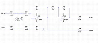
I came up with the simple method shown in the attached figure, time constants tbd but around 1 second (which can be increased if needed).
I'll be installing the servo next week...keep tuned for progress reports.
--------
I'm still amazed at how good this amplifier sounds with NO global negative feedback loop! The only negative (so far that I've noticed) to not having feedback is a gain delta between channels of a couple of dB (easily compensated for with the balance control)
--------
Way, way off topic:
I remember the first tube amp I built as a teenager in the late 60's, how great it sounded! Especially I remember how nice it SMELLED as it reached operating temperature. This amp I built has all of the same attributes. Phenolic circuit boards, residual solder flux, oxidizing dust, all these things volatilize and emanate into the air and the dry heat irradiating your face as you approach the glowing bottles, it's MAGIC, I say!
California Air Resources Board VOC regulations be damned! It's like an amazingly good stew simmering on the stove, or bacon on a Sunday morning, but better.
-----
(I can't say the same thing about the hand-me-down vacuum tube TV set my grandma gave me at around the same time period, however. It smelled of the liniment she used for her phlebitis!!!)
Regarding RFI filtering, I'll probably add a clamp-on ferrite or similar to the output leads, even though I don't live close enough to any high power transmitters that might cause any problems, if and when I decide to connect the NFB loop. Couldn't hurt.
I've already wired up a couple of servo boards, sensing the delta across the output terminals, and feeding a correction voltage back to the driver in a differential fashion. Your tip to eliminate one opamp is noted, if it turns out that it doesn't perform as imagined then I'll try your method.
I came up with the simple method shown in the attached figure, time constants tbd but around 1 second (which can be increased if needed).
I'll be installing the servo next week...keep tuned for progress reports.
--------
I'm still amazed at how good this amplifier sounds with NO global negative feedback loop! The only negative (so far that I've noticed) to not having feedback is a gain delta between channels of a couple of dB (easily compensated for with the balance control)
--------
Way, way off topic:
I remember the first tube amp I built as a teenager in the late 60's, how great it sounded! Especially I remember how nice it SMELLED as it reached operating temperature. This amp I built has all of the same attributes. Phenolic circuit boards, residual solder flux, oxidizing dust, all these things volatilize and emanate into the air and the dry heat irradiating your face as you approach the glowing bottles, it's MAGIC, I say!
California Air Resources Board VOC regulations be damned! It's like an amazingly good stew simmering on the stove, or bacon on a Sunday morning, but better.
-----
(I can't say the same thing about the hand-me-down vacuum tube TV set my grandma gave me at around the same time period, however. It smelled of the liniment she used for her phlebitis!!!)
Attachments
Incredible description of the tube amps, further the sound, the glow, "the smell...
How the olfactory sensations marks our remember forever. I agree with you Richard, I finish my first amp when I was 13 in the '71 and one of the senses that never share with anybody and now with your comments I flew there...
How the olfactory sensations marks our remember forever. I agree with you Richard, I finish my first amp when I was 13 in the '71 and one of the senses that never share with anybody and now with your comments I flew there...
Just about to start building a pair of M60 replicas, purchased a bunch of parts from someone here in NZ who hadn't managed to make a start on them, included a M60 Mk2 schematic, going to start with power supplies before moving on, three transformers included, one has 2x 110vac output, another 2x6.3vac and 245vac centre tapped outputs, and the last is 2x 25vac output, the last transformer is one I'm not sure of its purpose!
Think i just solved this while having a spa! The last transformer with 25vac is to power the heaters in the 6AS7G's in series, while the 6.3vac outputs on the other transformer are left for the heaters on the 6SN7G's!
Hello everybody , i am too going to attempt to build a set of M60 amps for my esl's ;-).
I emailed ralph to see if i could get the schematics and he revered me too this site were he said he posted it. I have looked true all the 64 pages but i can only find schematics of version 1.0 and 1.1 nothing newer then that, am i overlooking something or is that what he has posted ?
I emailed ralph to see if i could get the schematics and he revered me too this site were he said he posted it. I have looked true all the 64 pages but i can only find schematics of version 1.0 and 1.1 nothing newer then that, am i overlooking something or is that what he has posted ?
- Home
- Amplifiers
- Tubes / Valves
- What tubes for a OTL tube amp?