Merilainen is the most important read on current drive. Others are just explanations of damping factor.
Nelson's article is delightful. It is mostly about high efficiency full range speakers. He fails to mention though that the so-called "full range" is not exactly that, as these speakers do not handle well frequency extremes. I stopped reading when he proceeded to discuss equalization networks.
Nelson's article is delightful. It is mostly about high efficiency full range speakers. He fails to mention though that the so-called "full range" is not exactly that, as these speakers do not handle well frequency extremes. I stopped reading when he proceeded to discuss equalization networks.
Trying to wrap my head around it. From Ohm's Law, current and voltage are reciprocally proportional. The coefficient of proportionality is speaker's Z. If speaker had invariable Z, voltage or current drive wouldn't matter. But speaker's Z is very complex and highly variable, so it is a low quality voltage-to-current converter. That' the central point of Merilainen's article.For speakers, voltage is proportional to cone velocity. Current is proportional to force or acceleration. Since acceleration is the derivative of velocity, one needs to take the derivative of the usual audio V signal to feed to a current mode amplifier. If not differentiated, the usual voltage input signal will give you a 1/f response from a current mode amplifier driving a typical speaker. I haven't heard anyone mention this for current mode amplifiers, but maybe it is well known.
Merilainen is the most important read on current drive. Others are just explanations of damping factor.
Current drive is probably worth a separate thread. Maybe the old one here: https://www.diyaudio.com/community/threads/current-drive-amplifier.300321/ ? Or perhaps one looking at high output impedance valve amps - single-ended pentodes without global negative feedback anyone?
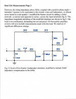
A speaker is like a motor with some parasitic elements. Looking at JHStewart's speaker model:Trying to wrap my head around it.
90 uH of voice coil leakage inductance. 7.5 Ohms of coil resistance. The 220 uF NP is the motor inertia (the elephant in the room ). And 60 mH is probably the air compressibility with 0.7 R the sound radiation resistance. The elephant in the room is the 220 uF with the series 7.5 Ohms. The 220 uF is the motor. V across it is velocity. I into it is acceleration. Changing V instantly would require huge current to accelerate it up to speed (thus changing V across it), but the coil resistance limits the current.
Speaker resonance is from the C (or inertia) and the 60mH (air compressibility).
For a capacitor I = C dV/dt or equivalently V = (Integral I dt )/C so obviously I is the derivative of V (and current is the derivative of voltage or velocity on the motor.
Physics gives the motor model with velocity ( Voltage) and acceleration ( current ) and mass or inertia (capacitance ), which has equivalent equations to the C and I and V electronic model.
Current leads to force or acceleration. Velocity is the integral of the force (f = ma or a = f/m )
Velocity = (integral accel)/m
So the current mode amplifier needs dV/dt drive while a voltage mode amplifier needs V.
So the current mode amplifier needs the derivative of signal voltage for its input. (ie, a differentiator at the input)
Leaving out the differentiator would lead to a 1/f response and 90 degree phase shift to the sound wave. d/dt Sine(omega) = omega times Cos (omega)
omega = 2 pi f
Last edited:

Thanks, that clarifies it. So, the prediction then is that response of speaker driven by high output impedance amplifier - from a standard signal source - will fall off at 1/F. Is that correct?
PWK's original homebrew amplifier, built immediately post-war (1945) still exists, and is at the Klipsch Museum. My friend itishifi.com is building a (safe! the original mounted all of the circuitry beyond the output valves in the speaker; three wires between, and all at B+) beautifully made copy of the circuitry, with inductors donated by Dave Slagle (!). It will be running into the original Klipschorn. Klipschorns factory fitted with this combination of crossover and output transformers were called Type B. The museum is worth the trip for those interested in the early history of HiFi and theater sound.It turns out there are a lot of gems in RDH. For example this intriguing tidbit on pg. 888.
All good fortune,
Chris
Last edited:
As always, much thanks to smoking-amp for a stunningly clear explanation of the model. Only a very deep understanding can give this kind of clarity. And make it look easy.
Always good fortune,
Chris
Always good fortune,
Chris
It appears that would be the case. Maybe JHStewart will have some comments on this.Thanks, that clarifies it. So, the prediction then is that response of speaker driven by high output impedance amplifier - from a standard signal source - will fall off at 1/F. Is that correct?
As always, much thanks to smoking-amp for a stunningly clear explanation of the model. Only a very deep understanding can give this kind of clarity. And make it look easy.
😎 Thanks for the accolade, but to be honest, I pretty much pulled the interpretation out of the air on this one. But it does seem to make sense.
Current drive (with the derivative fix) would then produce the same equivalent voltages at the speaker as voltage drive. Except for some effects on the parasitic elements. The 90 uH would be transparent, except for a little extra voltage swing. RDC would be the same. The derivative fix handles the C equivalently. I guess beyond the big C it would then still look like V drive to the rest ( 60 mH and 0.7 R ) due to its low impedance. Some subtle effects maybe.
Effects on the amplifier from speaker reverse generated EMF would certainly be different, largely ignored by the high Z drive I think.
The speaker suspension would be handled differently too. Hard landing ( V drive ) versus soft landing ( I drive ). The coil resistance fortunately keeps V drive from pushing the voice coil right out of the magnet assembly. Maybe negative resistance fixes for a conventional V drive amp can get you into trouble if taken too far. (besides possible oscillation )
There may be some similarity here to a shunt connected DC motor ( V drive ) and a series connected DC motor ( I drive ).
Last edited:
Remarkable! Here on DIY in less than a week we have shewn that the entire audio industry has gone the wrong way for the past 70 years. That has got to rank right up there with the discovery of gravity & the ability to slice bread with a machine! 😀
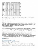
The simulator I pieced together 20 years ago is meant to check amplifiers, not speakers. It works well in that service. The response to an amp having DF a lot less that one is attached. And looks much like a typical pentode output, SE or PP without voltage NFB.
The other attachment is a speaker simulator by Ken Kantor that has been out there for a while. Complete with a good description.
Around 1960 HP bought a company in Boston called Sanborn. They were primarily in the Biomedical business but they also had a popular line of multipen strip chart recorders. The pen drivers are power galvanometers & have similar problems to magnetic loudspeakers. My recollection of the electronics was use of both PFB & NFB around the galvos. The math solution was by a 2nd order differential equation. Last time I managed to solve one of those was 50 years ago. In the meantime the most complicated math I ran into in my job was filling out the travel expense report. And by 20 years ago it was all on a spread sheet, just stuff the numbers in. So I won’t be solving any of those equations today!
Attachments

Re: DF with multi-way loudspeakers, I scavenged many defunct PSB 2-ways for crossover parts. Not one second low pass inductor had lower than 0.4 ohm resistance directly in series with the woofer. Add 0.1 - 0.2 ohms for speaker cables and amp and maybe another 0.25 ohms if it's a third order low pass and the typical amplifier output impedance quickly becomes a minor factor in woofer resonant control.
Re: P-P Schade, it lowered distortion in a triode-driving-pentode amp but distortion spectrum was third dominant. Feedback from the output winding resulted in second order dominant for the same overall percentage on the bench.
Simulations of output plate to drive cathode showed massive bass roll off, from memory 15 dB at 20 Hz. It wasn't really investigated further so may my sim was incorrect?
Recalling more on those power galvos, they were not the same as a common speaker,
There is a 2nd winding on the motor used to provide part of the FB signal direct from the galvo.
Aren't there some active speakers on the market today where the driver amp is in the box
& the speaker does have another winding to form part of the FB network? That would be
the 2nd order dim equation.
I'll have a look, I think there is something covering those galvos in a early HP Journal.
I remember there were car speakers with twin VC. But I am wondering what difference would it make between FB from an auxiliary VC or from the main one?
I have a 12 inch speaker with dual VC. Probably intended for dual amplifier drive.
It could be used for N Fdbk I guess. If the coils don't directly couple too much.
The second coil allows for an accurate Fdbk signal, without the Rcoil voltage drop of the driven coil. Same goes for separate (no drive current thru ) Fdbk windings on an OT.
It could be used for N Fdbk I guess. If the coils don't directly couple too much.
The second coil allows for an accurate Fdbk signal, without the Rcoil voltage drop of the driven coil. Same goes for separate (no drive current thru ) Fdbk windings on an OT.
Last edited:
Speaker stiffness and air stiffness. The "spring" the mass (capacitor) bounces on.And 60 mH is probably the air compressibility
Because a standard loudspeaker in current drive tends to be one big boom, these rigs are often open-back baffles, and so some enthusiasts will say "What compresion?" But there's always stiffness in the suspension.
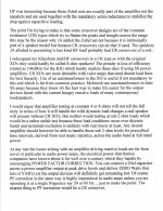
- scale down plus try to compensate the phase of the output signal;
- compare the two previous signals, obtaining as an output only the difference between the two, so the distortion;
- amplify the resulting distortion and send it to the other side of the phase splitter as gnfb.
@ zintolo:
completely off topic, but here's something similar that has been done;
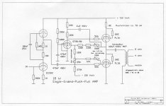
T.C.Murray's amplifier; it is SE in nature although it looks totem-pole push-pull at first glance, but it is not; the pentode in the middle acts as an error amplifier comparing input with scaled down distorted output, and sends the result (i.e. distortion) to the upper output valve; the distortion cancellation thus happens right at the output node ...
attachments show Murray's paper and an implementation by Wim deHaan;
Broskie also discussed it in his blog: https://tubecad.com/2004/blog0024.htm
Attachments
A horn gives the driving surface a better impedance match. Room air is very low impedance, almost a short, to massive moving diaphragms. A horn "transforms" low impedance room air to better match the diaphragm's inherently higher mechanical impedance. This better match damps diaphragm motion, reflected through the motor as a more resistive load, first acoustically, then mechanically, then electrically.How is a horn capable of flattening the impedance curve?
All good fortune,
Chris
@ zintolo:
completely off topic, but here's something similar that has been done;
Thank you Sorento. Yes, it has been done previously indeed.
To keep my French and Spanish oiled I read/write on different forums, and this is something that has been developed and used on two french forums, then applied to commercial products as well. With this gnfb concept they get very low distortions and high DF (above 20, sometimes above 100) on SET and PP as well, keeping the 2 gain stage. I tried to propose it on this forum few times, but it has never breached other people's hearts.
This below is the block diagram, taken from here: http://www.forum-bleu.com/t1430-correction-differentielle-un-nouveau-ne-en-se#28502
Last edited:
Thank you Chris! I guess the fact the most speakers are rear loaded horns is that they were historically easier to be built, whilst nowadays with 3D printing it is easier to load the speaker with horns on both sides.This better match damps diaphragm motion, reflected through the motor as a more resistive load, first acoustically, then mechanically, then electrically.
"Rear loaded horns" is a modern misuse of the term "horn", and are more in the category of transmission line loading than horn coupling. Imagine a piston in a wall: half of the piston's radiated energy goes to each side of the wall, and the two sides' radiated energies are in opposite polarity. The only (simple, primitive) way to use the energy from the "wrong" side of the wall requires that its polarity be inverted. Bass reflex boxes do this through a narrow spectrum near box resonance (imagine holding a spring with a rock at its other end - moving your end of the spring up and down you can find a rate where your hand is moving up as the rock is moving down - polarity inversion), but no horn can invert polarity. We're straying very far from the thread's topic.
All good fortune,
Chris
All good fortune,
Chris
- Home
- Amplifiers
- Tubes / Valves
- What Schade Feedback Leaves Behind