Many here are under the assumption that a typical loudspeaker system is easy to define or model. Most speaker manufacturers furnish a cute little graph of impedance VS frequency. This graph is a little hint at what to expect, but rather useless in the real world. This graph was made by a single tone sweep at a relatively low level. We don't tend to listen to those. Music is a complex collection of pitched tones and percussive sounds that interplay with each other and often create conflict in a speaker system.
A single driver speaker system consists of a coil moving in a magnetic field that is attached to a cone or other means of turning coil movement into air movement. This is akin to a PM motor (coil / magnet) with a load (the cone / air). Like all PM motors, this one is also a generator. If you gently push on the speaker cone you will see a voltage develop across the terminals of the speaker driver. The music that is pushing the cone around against air and cabinet related damping is also generating a counter EMF in the voice coil. The speaker is generating a voltage that is being fed back into the speaker terminals of your amp.
If the amp does not employ any feedback from the OPT (primary or secondary) to preceding stages, the counter EMF fed backwards into the amp's output will mostly be dissipated in the amp's output impedance, possibly generating some low level IMD due to non linear elements in that path. If the amp employs GNFB from the speaker terminals AND has a non zero output impedance, some of this counter EMF will be forced into the feedback loop where it will try to correct something that didn't happen in the amp. This can generate all sorts of non musical signals, usually at low levels.
Obviously, I have described the two extremes for a single driver speaker system. Add more drivers and a crossover network and things get far more complicated.
About 20 years ago I jumped down this rabbit hole with both feet. I took test recordings with a bass guitar generating a near perfect sine wave and imposed a snare or kick drum hit on top of it. All were 44/16 digital recordings that I made myself in the late 1990's. I moved the drum hit around on the bass guitar wave such that it either attempted to instantaneously reverse the speaker cone's travel, or push it further along on its existing path. I tried this with several different speaker systems and amps including a crude DIY no feedback solid state amp that had no problem pushing 10 amps into a dead short. I spent nearly a year digging myself deeper and deeper down the rabbit hole with no firm conclusions other than that speaker curves are a joke especially near resonance, and a gig 15 inch woofer can exhibit a near zero, or possibly even negative impedance when asked to reverse it's travel at a relatively high volume level. I wisely backed out of the rabbit hole, filled it back in and covered up my tracks, never to return. No attempts to test above a few hundred Hz were made nor were multiple driver systems tested other than my Yamaha NS-10M's which were largely unpredictable.
This effort led me to a few conclusions. I try to minimize the output impedance of all amps I make without piling on GNFB. DF's in the 10 range are good enough unless you are trying to fill a stadium with sound with large speakers. Large amounts of GNFB from the speaker terminals in a tube amp with a less than stellar OPT may do more harm than good due to phase shifts in the LF region. I also learned not to put a Shure SM-57 inside the kick drum if you ever want to use it again.

Thanks, you answered a question I forgot to ask before: higher wattages and heavier cones need more damping because you have more kinetical energy in action. So a horn loaded fullrange small cone could permit to have lower damping factors due to the more stable impedance and lighter cone?DF's in the 10 range are good enough unless you are trying to fill a stadium with sound with large speakers.
Yes, a 15 inch pro audio woofer with a 4 inch voice coil has much more moving mass than a single 5 or 6 inch full range speaker. Stopping and reversing the travel of the big speaker takes far more energy than the small one. As with a PM motor, just shorting the terminals of the woofer makes it harder to move the cone (dynamic braking). DF is a partial short across the speaker. Multiple large drivers in parallel will reduce the total DCR, but this is a moot point if all of them are producing the same counter EMF. There are more factors than just driver size in play too. Some speakers have better internal damping than others.Thanks, you answered a question I forgot to ask before: higher wattages and heavier cones need more damping because you have more kinetical energy in action. So a horn loaded fullrange small cone could permit to have lower damping factors due to the more stable impedance and lighter cone?
Imagine throwing your car into reverse at 30 MPH or so (not possible on a modern car). Either the system will absorb the shock without damage and reverse it's travel within a certain distance or it will break, temporarily or permanently. Usually the breakage involves a temporary loss of traction as the tires can't absorb the shock. Most amplifier / speaker systems fall in same category, though some can misbehave in the "loss of traction" time period. I built some KT88 based push pull amps back in the late 90's that produced a burst of oscillation during "loss of traction." An RC snubber across the OPT primary fixed it. Throw a fully loaded semi truck into reverse at speed and bad stuff is bound to happen.
Imagine throwing your car into reverse at 30 MPH.
----------------------------
I did by mistake, didn't have to imagine that. It was a 64 Chev Wagon with the Super 6 under the hood.
The transmission survived but all the vacuum lines to the engine blew off. A company car, it still got me to my customers! 😀
----------------------------
I did by mistake, didn't have to imagine that. It was a 64 Chev Wagon with the Super 6 under the hood.
The transmission survived but all the vacuum lines to the engine blew off. A company car, it still got me to my customers! 😀
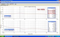
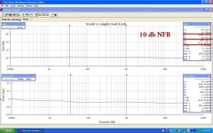
Here are the plots of response of a 6L6 driving that speaker simulator I use connected first as a triode with no NFB, Then FB applied.
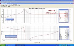
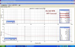
And the same for a pentode. As a pentode the tube is simply a current source of so many mA / Volt in parallel with its plate resistance rp.
So the response without NFB simply follows the impedance curve of the load. Just like PRR said.
This was put together on EWB for a presentation at the local Geezers Collectors Club in 2017. 🙂
Attachments
-
 10 Triode w Complex Load No NFB w Captions.jpg136.5 KB · Views: 121
 -
 20 Triode w Complex Load 10 db NFB with Captions.jpg129.9 KB · Views: 119
 -
 50 Pentode w Complex Load no NFB Corrected OPT & Captions.jpg140.3 KB · Views: 102
 -
 60 Pentode w Complex Load 18.2 db NFB Corrected OPT & Captions.jpg137.2 KB · Views: 106
Tubelab - you nailed it. Speaker is a very complex and active load that generates a lot of non-harmonic distortion in addition to HD and IM; NFB actually adds to speaker distortion rather than mitigating it. In the end, it's current through the VC, not voltage across it, that produces sound. I will make the last step in your line of reasoning: nfb, even the local one, is a bad thing for speaker-generated distortion.
So now we are promoting the kitchen radio with its 35L6 unbypassed cathode resistor in a small open back box.
Or the floor console with its shiny SW dial & magic eye.
If current drive was a great idea, why was the scheme not pursued as what we see in amplifiers today, whether SS or Toobz?
Those radios from the 30s & 40s got their bass response thru the magic of a poor DF amp & loudspeaker resonance.
But after a couple of beers no one cared. 😀
I'm in favor of both THD & IMD measurements. Many are here at DIY done on amps I've built
On speakers I've done frequency vs impedance plots. But I've never done distortion on speakers. I'll leave that to the experts.
I couldn't locate my file, but here is somewhat fuzzy schematic:To add on the Belvedere, this is a quote from a 1947 Magnavox promotional:
----------------------
Anybody got a schematic of that or something similar?
There is an example of a PP 6L6 output section in Beitmans, a pre WW2 Philco receiver.
antiqueradios.com/forums/viewtopic.php?f=10&t=235554
Inverter is a little weird, but I don't see any nfb, global or local.
Unfortunately, the paradigm of resonant boxed speakers needing low output impedance amplifiers took such strong root that it almost completely displaced all other approaches. As well as disdainful belief that anything with less than 0.1% THD and bandwidth short of 20-20,000 is not worth even looking at.If current drive was a great idea, why was the scheme not pursued as what we see in amplifiers today, whether SS or Toobz?
On this forum particularly, there is sad, almost schizophrenic disconnect between amplifier people and speaker people. Neither side seems to realize that both must be regarded together, and must synergize in order to achieve optimal performance.
Last edited:
And typically 1/2 the power output for the same dissipation (cost).Doesn't seem like a Mfr would want such a tube. A cheap 12GC6 or 6FW5 has very similar curves but with 1/2 the Rp.
Go to the old books. All this was hashed-out in the late 1930s. Notably Langford-Smith 3rd (or 4th). Chapter "The relation between the loudspeaker and the bottle"
From the Late 1930s on in the english-speaking world, Langford-Smith and others published on amplifiers driving loudspeakers. Greatest hits include:Go to the old books. All this was hashed-out in the late 1930s. Notably Langford-Smith 3rd (or 4th). Chapter "The relation between the loudspeaker and the bottle"
Audio Engineering, March 1951 and April 1951, Albert Priesman, "Loudspeaker Damping", parts one and two
Radiotron Designer's Handbook 4th ed, Fritz Langford-Smith, 1953, Chapter 21 "The Network Between the Power Valve and the Loudspeaker", pages 880-889
Radio Electronics, December 1953 and January 1954, D.J. Tomcik (Electro-Voice), "Missing Link in Speaker Operation", parts one and two
Electronics World, January 1967, George Augsperger (JBL), "The Damping Factor Debate"
Vacuum Tube Valley, Issue 18, 2002, Lynn Olson, "The Amplifier-Speaker Interface", pages 30-34
Current-Driving of Loudspeakers, Esa Meriläinen, 2010, pages 102 to 107 and then pages 111 and 112 for fun
The state of play was pithily summarised by Lynn Olson:
On this forum particularly, there is sad, almost schizophrenic disconnect between amplifier people and speaker people. Neither side seems to realize that both must be regarded together, and must synergize in order to achieve optimal performance.
Here I’ve read the suggestion to chase negative-phased second harmonic to counteract the inertia of the cone: the wave is (a little bit) flatter on the peaks and it’s the inertia of the cone that makes it again a sinusoidal. This would permit to have lower damping (the cone needs to divert from the electric signal on peaks), so stick on local feedback only.
I profit of the partecipation of such knoledged people to ask a question on something I'm working on:
Imagine a two stage PP amp: phase splitter, power tubes, output transformer.
I want to compare the (scaled down) output signal to the input signal.
The difference between the two is the distortion that the amp produces.
I want then to apply as voltage negative feedback, the distortion only.
What I'm doing now is:
As by now I'm thinking to use a simple OPAMP to compare and amplify, but a triode can be used as well.
Is there any smarter and more precise way to compare the input and output signals?
Thanks
Imagine a two stage PP amp: phase splitter, power tubes, output transformer.
I want to compare the (scaled down) output signal to the input signal.
The difference between the two is the distortion that the amp produces.
I want then to apply as voltage negative feedback, the distortion only.
What I'm doing now is:
- cut radio frequencies of the input signal;
- scale down plus try to compensate the phase of the output signal;
- compare the two previous signals, obtaining as an output only the difference between the two, so the distortion;
- amplify the resulting distortion and send it to the other side of the phase splitter as gnfb.
As by now I'm thinking to use a simple OPAMP to compare and amplify, but a triode can be used as well.
Is there any smarter and more precise way to compare the input and output signals?
Thanks
Bondini; Love that reference list. It turns out there are a lot of gems in RDH. For example this intriguing tidbit on pg. 888.

Very clever. Might be some advantages to such a network even for separate tubes for each range.
Very clever. Might be some advantages to such a network even for separate tubes for each range.
Indeed, wide - band output stage with a single transformer puts conflicting demands on transformer design that are virtually impossible to reconcile. By contrast, if the audio band is split into 2 or 3 sub-bands, transformers for each sub-band can be easily optimized. Importantly, such arrangement allows ditching speaker-level crossover.Bondini; Love that reference list. It turns out there are a lot of gems in RDH. For example this intriguing tidbit on pg. 888.
View attachment 1062057
Very clever. Might be some advantages to such a network even for separate tubes for each range.
https://worldradiohistory.com/Archive-All-Audio/Archive-Audio/50s/Audio-1951-Mar.pdfAudio Engineering, March 1951 and April 1951, Albert Priesman, "Loudspeaker Damping", parts one and two
https://worldradiohistory.com/Archive-All-Audio/Archive-Audio/50s/Audio-1951-Apr.pdf
http://www.tubebooks.org/books/rdh4.pdfRadiotron Designer's Handbook 4th ed, Fritz Langford-Smith, 1953, Chapter 21 "The Network Between the Power Valve and the Loudspeaker", pages 880-889
https://www.pearl-hifi.com/06_Lit_Archive/02_PEARL_Arch/Vol_05/Sec_23/1385_Preview.pdfRadio Electronics, December 1953 and January 1954, D.J. Tomcik (Electro-Voice), "Missing Link in Speaker Operation", parts one and two
https://www.cieri.net/Documenti/JBL/Documenti tecnici/JBL - The Damping Factor Debate (1967).pdfElectronics World, January 1967, George Augsperger (JBL), "The Damping Factor Debate"
https://worldradiohistory.com/Archi...m-Tube-Valley/Vacuum-Tube-Valley-Issue-18.pdfVacuum Tube Valley, Issue 18, 2002, Lynn Olson, "The Amplifier-Speaker Interface", pages 30-34
I haven't found this article, do you have a link for it? ThanksCurrent-Driving of Loudspeakers, Esa Meriläinen, 2010, pages 102 to 107 and then pages 111 and 112 for fun
I haven't found this article, do you have a link for it? Thanks
No pdf - you can buy it print-on-demand from the author: https://www.current-drive.info/
Nelson Pass writes on the subject here: https://www.firstwatt.com/pdf/art_cs_amps.pdf
The 7355 has a 500V B+ limit. 6V6 has a 350V limit. The other two tubes (12GC6, 6FW5 ) have a 770V B+ limit. Only the heater power holds them back from high efficiency at high Volts. Though Tubelab does get remarkable power from Sweep tubes typically.
-------------------------
For speakers, voltage is proportional to cone velocity. Current is proportional to force or acceleration. Since acceleration is the derivative of velocity, one needs to take the derivative of the usual audio V signal to feed to a current mode amplifier. If not differentiated, the usual voltage input signal will give you a 1/f response from a current mode amplifier driving a typical speaker. I haven't heard anyone mention this for current mode amplifiers, but maybe it is well known.
- Home
- Amplifiers
- Tubes / Valves
- What Schade Feedback Leaves Behind