I've got R13 at 0R1, should it be 0R15 ?
If I go down the avenue of fitting a 10K multi-turn pot I might be able to adjust for that ?
If I go down the avenue of fitting a 10K multi-turn pot I might be able to adjust for that ?
Leave R13 at 0,1Ω, it's part of the current limiting.I've got R13 at 0R1, should it be 0R15 ?
If I go down the avenue of fitting a 10K multi-turn pot I might be able to adjust for that ?
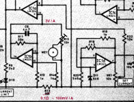
Replace R15 by a 10k potmeter. ME1 has to have 10V full scale or more sensitive.
Mona
Attachments
Hi Katie and Dad, was this power supply originally a magazine project? The schematic drawing appears to be in the style of Practical Electronics.
Steve.
Steve.
Make sure to look at the MOSFET SOA, then take it with a grain of salt. As a hint, with lower voltages in the 50 volt range, the FQA8N90C-F109 handles linear operation very well. I tested it to 5A @ 40V for 1 minute, and it held up fine.
It isn't great at high voltages, taking maybe 100mA at 450V, far less than its datasheet would suggest. For whatever reason, ON Semi doesn't believe that MOSFETs suffer from secondary breakdown, because the SOA curve shows absolutely none. Actual testing of devices shows that this is a load of manure.
Also, be careful of oscillation with this type of circuit.
Hi Katie and Dad, was this power supply originally a magazine project? The schematic drawing appears to be in the style of Practical Electronics.
Steve.
I got the article from Magenta Electronic Designs who probably designed it in the first place.
Hmmm, the idea of using the 10K pot isn't working.
I can calibrate the meter at any one setting but it then doesn't track correctly.
R15 is short circuit so there is just the 10K pot across the output of IC1b.
If the IC is outputting 3V/A then with the pot set at 33% the wiper should see 1V/A.
It is a DPM so the meter impedance should be very high.
I can calibrate the meter at any one setting but it then doesn't track correctly.
R15 is short circuit so there is just the 10K pot across the output of IC1b.
If the IC is outputting 3V/A then with the pot set at 33% the wiper should see 1V/A.
It is a DPM so the meter impedance should be very high.
Last edited:
The only thing that comes to my mind is that the DPM is loading the 10K pot and isn't an ideal infinite resistance.
Digital 0.36inch LED Display 5 Bits DC 0-33.000V Voltmeter Voltage Meter L&6 | eBay
Digital 0.36inch LED Display 5 Bits DC 0-33.000V Voltmeter Voltage Meter L&6 | eBay
Last edited:
The project is working perfectly after all these years with the IRFP240. It is just the Ampere meter which isn't making any sense.
The output current is constant and is regulated as expected. I can monitor it out of the PSU with my DMM.
The output current is constant and is regulated as expected. I can monitor it out of the PSU with my DMM.
The meter indicates a multiplyed voltage drop on R13. There is still a current, without load, from the circuit following R13.So the meter never reaches zero, but that is a very small error probably ~10mA (changes with voltage setting).
Since the current limit circuit uses the same voltage to compaire against the current setting (range from 0 to allmost 10V) in IC1a, I supose with current limit set to zero the supply goes in overload without load.
Mona
Since the current limit circuit uses the same voltage to compaire against the current setting (range from 0 to allmost 10V) in IC1a, I supose with current limit set to zero the supply goes in overload without load.
Mona
Now that I looked again at the schematic, I have misread the value of R11 😱.
Looks like 30k but it seems to be 39k.
That doesn't change the principle but the numbers. It's not 3A/V but 3,9A/V.
And also the range of the current limit, now 0 - 2,5A.
Mona
Looks like 30k but it seems to be 39k.
That doesn't change the principle but the numbers. It's not 3A/V but 3,9A/V.
And also the range of the current limit, now 0 - 2,5A.
Mona
So what readings do you get with what loads ?The meter is not marginally out on tracking, it is massively out.
Mona
I've got a 150R 20W load resistor in series with my DMM.
DMM Reading vs Meter Reading
100mA 100mA - Calibration Point
50mA 70mA
20mA 42mA
200mA 200mA
DMM Reading vs Meter Reading
100mA 100mA - Calibration Point
50mA 70mA
20mA 42mA
200mA 200mA
I've just ordered a pair of 50W 20R resistors, it'll be interesting to see what happens as the current increases.
The problem does look as though it is in the lower output current region ?
The problem does look as though it is in the lower output current region ?
It looks like there is about 20mA of current in the circuit after R13.I've got a 150R 20W load resistor in series with my DMM.
DMM Reading vs Meter Reading
100mA 100mA - Calibration Point
50mA 70mA
20mA 42mA
200mA 200mA
With no load do still read ~20mA ? If so we have to pull up the negatieve side of the meter to bring the reading to zero at no load.
It will allways be an aproximation because the disturbing current isn't a constant.
Mona
- Home
- Amplifiers
- Power Supplies
- What MOS-FET ?