I've just making up a 1R3 resistor in preparation for some more experimenting.
I'm going to install a 4K7 multi-turn pot across this shunt and measure the voltage at the wiper of the pot. I might even use a 1K multi-turn.
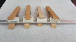
I've epoxied the resistors to an aluminium strip, 1 to aid heat dissipation and 2 to aid thermal stability.
3 x 0R33 + 1 x 0R27. They are all rated at well below what they will expect at 2.5A.
2.5 x 2.5 x 0.33 = 2W (They are rated at 5W)
2.5 x 2.5 x 0.27 = 1.6W (It is rated at 3W)
I'm going to install a 4K7 multi-turn pot across this shunt and measure the voltage at the wiper of the pot. I might even use a 1K multi-turn.
I've epoxied the resistors to an aluminium strip, 1 to aid heat dissipation and 2 to aid thermal stability.
3 x 0R33 + 1 x 0R27. They are all rated at well below what they will expect at 2.5A.
2.5 x 2.5 x 0.33 = 2W (They are rated at 5W)
2.5 x 2.5 x 0.27 = 1.6W (It is rated at 3W)
Attachments
Last edited:
The extra 1R3 in the output leads won't affect the PSU at all as the voltage output sense and voltage measurement is at the output sockets.
The problem is where to put your shunt.If you put it before the voltage sensing then there is still the problem of non wanted extra current in the shunt.If you put the shunt between load and supply the voltage on the load will change with the current.That should do the trick.
I'm going to use 10 x 10R 1W 1% resistors in parallel to make the shunt, that'll be more accurate than a single W/W.
You can try to compensate the error current, that isn't 100% right because it varies.
Like this, first adjust the zero with the 50Ω trimpot then calibrate with the 10k.Repete a few times, they influence each other.
Mona
Attachments
The voltage sensing is taken from the output terminals.
The sensing circuit draws approx. 1mA, I can live with that error.
The sensing circuit draws approx. 1mA, I can live with that error.
Last edited:
But that sensing is in reference to the voltage set circuit.Now your output voltage is current dependent.The voltage sensing is taken from the output terminals.
The sensing circuit draws approx. 1mA, I can live with that error.
Mona
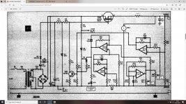
Mona, the PCB is really compact and not easy to modify, the project is also very tight in the case.
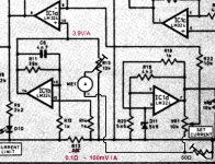
The schematic isn't entirely accurate to how it is actually wired up.
This is a more accurate interpretation of how it is implemented.
This is a more accurate interpretation of how it is implemented.
Attachments
Last edited:
If you can do the current measure on the positive side most of the problems are avoided.There you have only the 0...1mA from the voltage sensing. The current from the voltmeter is probably to small to bother.
Only thing left is the 1,3x2,5=3,25V you lose, is there enough from the rectifier to cope with that ?
Mona
Only thing left is the 1,3x2,5=3,25V you lose, is there enough from the rectifier to cope with that ?
Mona
If you can do the current measure on the positive side most of the problems are avoided.There you have only the 0...1mA from the voltage sensing. The current from the voltmeter is probably to small to bother.
Only thing left is the 1,3x2,5=3,25V you lose, is there enough from the rectifier to cope with that ?
Mona
You replied before I added the picture. If you jump back one post to #48 you will see that we are on the same wavelength.
I'm just testing the bare bones of the power supply, it isn't finished yet.
It is quite comfortable with an output of 15V @ 1.6A, the heatsink is running at about 50C.
I think it might struggle to produce 5V @ 2.5A.
Even with a huge heatsink I think at the extremes it might need more pass devices to share the load ?
It is quite comfortable with an output of 15V @ 1.6A, the heatsink is running at about 50C.
I think it might struggle to produce 5V @ 2.5A.
Even with a huge heatsink I think at the extremes it might need more pass devices to share the load ?
Attachments
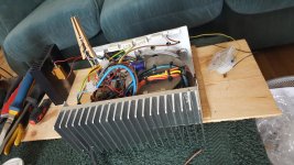
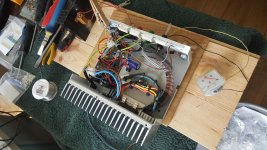
You'll notice the extra winding on the transformer and the bridge / cap on top of the toroid. These form the auxiliary supply required by the DPM.
I'm waiting for another DPM to act as a voltmeter, the moving coil meter is only there to indicate approximate output while I'm testing it.
Unfortunately I don't know the thermal rating of the heatsink, it is a cut down repurposed heatsink from an older project.
Even though the project is in a steel case, the MOS-FET is mounted directly to the heatsink through an aperture in the steel.
- Home
- Amplifiers
- Power Supplies
- What MOS-FET ?