The modified schematic
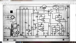
Here's the modified schematic.
I've added the trim-pot across the shunt resistor as it is difficult to get 1R0 / 10W at 0.1% accuracy.
The 1R2 allows for the builder to trim any errors out of the current reading.
There is still a tiny error due to the sensing circuit drawing a minute current but it is the order of a few mA.
Attachments

Last edited:
I was hoping that someone would comment on how the original design would have been able to shed some 100W of heat from a single output device.
The DPMs have a wide operating voltage, I only used 9V1 as that is what I had on hand.
I don't think there will be much difference in the two displays at 12V and 9V.
I don't think there will be much difference in the two displays at 12V and 9V.
I was hoping that someone would comment on how the original design would have been able to shed some 100W of heat from a single output device.
By using a MOSFET with a big die area mounted in a TO-3 package with its large thermal contact area mounted on a huge heatsink? And making sure to use a MOSFET without Spirito instability, of course, but MOSFETs from before the 1990's generally didn't have that.
It couldn't, the HP part had a max PD of 90W. I would think that the original project documentation would have had a graph or curve showing max voltage and current output vs dissipation.I was hoping that someone would comment on how the original design would have been able to shed some 100W of heat from a single output device.
I've got the original article, there is no mention of maximum dissipation curves.
It simply says 0-25 V at up to 2.5A.
It simply says 0-25 V at up to 2.5A.
It's unlikely that I would ever need 1V at 2.5A.
5V at 2.5A is a real life load. At that load the IRFP240 would be dissipating 87.5W.
5V at 2.5A is a real life load. At that load the IRFP240 would be dissipating 87.5W.
The IRFP should be good for 150W but will the heatsinking be adequate ?
I could mount a couple of fans to increase the airflow.
I could mount a couple of fans to increase the airflow.
Would it be possible to get a copy of the article from you? Thanks.
If you PM your e-mail address I'll send you a copy.
I have had permission from the originator of the design.#
Hello,
There's no problem using parts of the article as far as Magenta is concerned. We retained copyright on this and all of our published projects.
Some of the artwork and all of the typesetting was produced by EPE magazine so I think an acknowledgement to us and to EPE would be expected. Otherwise any interest in the design and article is welcome.
I'm particularly fond of this project for several reasons. The first is that the use of a MOSFET with practically no gate current demand allowed a simple voltage doubler to provide plenty of gate drive. The second is the constant current zener diode reference - a simple op amp stage producing a remarkably stable 10 volt output. The third is that the whole design runs with a single cheap LM324. Oh, and the fact that that the output voltage and current limit turn down to Zero.
Good luck with your tweeks! I think the current and voltage meters are referenced to 0V so it should be straightforward.
Please let us know how you get on.
Best Regards
Brian
I've had to make a few slight adjustments.
The DPMs draw slightly more than 20mA, the 2K7 in the Zener line for the voltmeter starves the DPM of power. I've had to reduce it to 1K0 and up the rating to 3W.
The DPMs can only read up to 30V. I've added a 3K3 at the top end of VR2 (Voltage adjust) to limit its range within that of the meters.
The DPMs draw slightly more than 20mA, the 2K7 in the Zener line for the voltmeter starves the DPM of power. I've had to reduce it to 1K0 and up the rating to 3W.
The DPMs can only read up to 30V. I've added a 3K3 at the top end of VR2 (Voltage adjust) to limit its range within that of the meters.
You can play with the value of the 3K3 resistor to suit your DPM.
I eventually used 2K7.
The circuit with a 30V transformer and IRFP240 can actually produce about 37V.
I eventually used 2K7.
The circuit with a 30V transformer and IRFP240 can actually produce about 37V.
Attachments
Last edited:
- Home
- Amplifiers
- Power Supplies
- What MOS-FET ?