The problem is very simple, the box is just too small, you are attempting to run a 10" in .3 cubic feet, and a driver not suited to small space at that. These model quite poorly for anything under 60hz in an enclosure that small
You'll have much better success with 2 Sundown subwoofers (or similar) designed for very small enclosures and even then you'll want to give each sub at least 1 foot each.
Sent from my iPhone using Tapatalk
You'll have much better success with 2 Sundown subwoofers (or similar) designed for very small enclosures and even then you'll want to give each sub at least 1 foot each.
Sent from my iPhone using Tapatalk
Which constant are you referring to?
These equations just describe the non-linearity of the air compliance. That's nothing to do with the driver(s). Total distortion will need to take into account the distortion of the driver and electronics as well.
But I don't think distortion alone would cause a "boxy" sound. Can you measure the impedance response of the subwoofer and post that here?
The constant is 1.4. It's the first number that enters the formula.
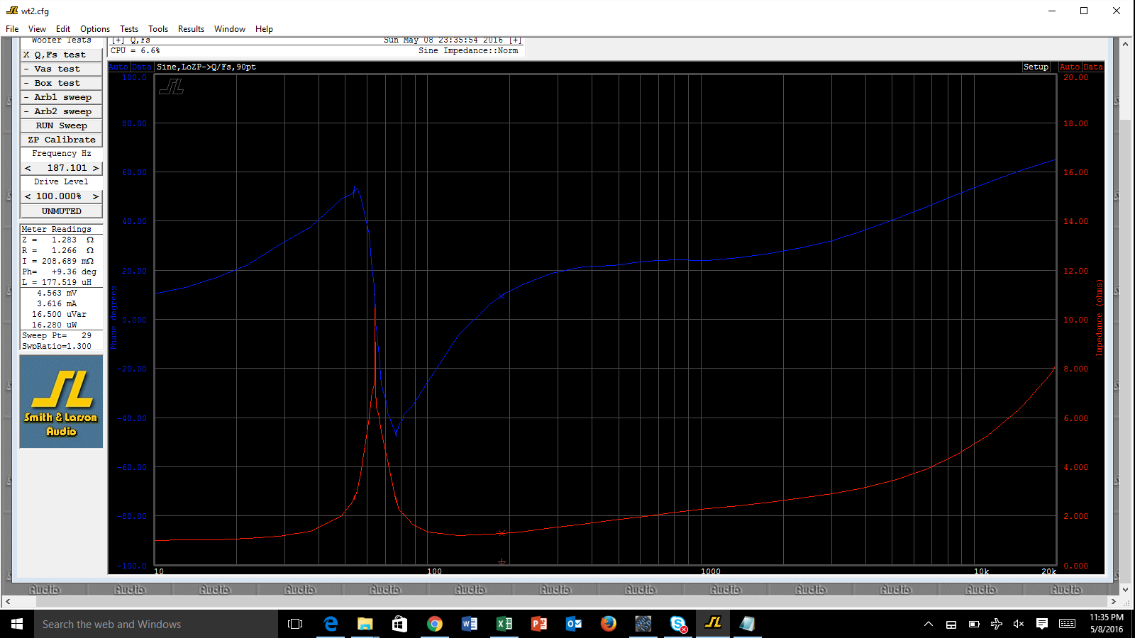
Here is the woofer tester 2 result:

aiming for 1 ohm speaker just because an amplifier claims its max power at that point is playing folly. ( what about batteries and charging? ) i'd aim for 2 ohms max and settle for 1000W peaks🙂 banana jacks /plugs are rated for heat rise at ~ 20A and that's just for the best ones. Get a good 4 wire ohm meter check all the wires and connections i'd bet dollars to donuts you'd be lucky to measure 1000W steady state with your set up. (do it... I dare you)
its good to design with plenty of power headroom even with conservative specs but car audio is well known for ambitious power numbers de-rate stuff by 1/2 to 1/4 . it's not easy figuring Q accurately with low ohms, everything is higher resistance than you thought ( when you measure it correctly) heck I recently bought some "high quality" silicone wire and it measured double what the claimed copper AWG tables said.
get a couple of low ohms test resistors <1% and / calibrate your testing , then re adjust Q with wiring added ( even the amplifier is not zero ohms at its connectors)
Well, the power is there for short bursts. It's nice to not have to worry about clipping. The wires are really short and thick so I doubt much gets lost in the transmission. I'm running 8ga wire to the sub box and 12ga internally. Total wire length is only 2 feed to the box from the amp. The amps was bench tested at over 2,500 w @1 ohm and less than 1% THD. This is a good one.
The Corvette has a massive alternator, I just upgraded the battery to an AGM, and amplifiers have continuously variable power supplies, but still in the analog domain. Class G/H.
The tests above are done by clipping the test leads to the box connection so it takes into account every wire except the 2 foot run of 8 ga to the box, which is actually a power wire not a speaker wire. Very thick stuff.
I've put together everyone's input and came up with the following battle plan. I will pursue the options in this order. If the first fails to satisfy, I'll go to the next.
1st option is to replace the 8 Vifas with 4 Seas L26RO4Y. The Q will drop from 1.07 to .56. SPL will be higher than the Vifas anywhere under 38hz for up to 3db gain at 20hz. I know from Seas the suspension has been stiffened in this 4 layer model vs. the 2 layer and the CMS is low enough to work in a tight sealed box.
2nd option is to add bass traps. I will not add bass traps unless the Seas really need them because they will take up box room.
3rd option is to mount all 8 Vifas in isobaric. The Q will drop from 1.07 to .64. SPL will be the same in the 20s but lower anywhere up for up to 4 db loss at 60hz.
That just seems like an awfully small box for 8 subs. The most delicious bass I ever made was with a single 10" in 2.5 cubic feet. F3 was below 40 Hz before cabin gain, so while it wasn't at all flat, it wasn't boomy, just thick deep solid bass. Q was above 0.7, since I'd designed the box for 2 of those woofers isobaric, then decided to try it with one temporarily. So, I'm a bit skeptical about using high f3 and counting on cabin gain to make it flat.
No doubt it is very little airspace per driver, it is uncommon. As tested in car, the frequency response is great, F3 is at ~18hz. The group delay is below audible thresholds, and exceptionally good bellow 60hz. I knew the Q was going to be around 1 before building this and I couldn't find a good reason not to do it. This much surface area is great for both SPL and low non-linear distortion.
The tough part is putting my finger on why it didn't work perfectly. If it's not linear distortion, non-linear distortion, or group delay, then what is it?
The problem is very simple, the box is just too small, you are attempting to run a 10" in .3 cubic feet, and a driver not suited to small space at that. These model quite poorly for anything under 60hz in an enclosure that small
You'll have much better success with 2 Sundown subwoofers (or similar) designed for very small enclosures and even then you'll want to give each sub at least 1 foot each.
Sent from my iPhone using Tapatalk
That's really the question, how are small box subwoofers designed differently than others?
seeing that you've already chosen sealed, you're already on the path to superior SQ. i don't have thiel small tech saavy to add to your search, but the worst thing that could happen is that you have too little internal volume and suffer bass rolloff, but ANYTHING'S better than the multiple forms of distortion you get from ports.
I certainly subscribe to this school of thought. I would use a port design only in a desperate situation. I did however buy the passive radiator from Seas to play around with in a separate box. 😱
Id target lower Q for high cabin gains, normal rooms sound fine with closed box Q~ 0.9/40-50Hz, cars maybe not. I think choosing cross over frequencies and gains for the best SQ (for the types music you listen to) in you car is best done by ear, IME Crossing too low means the subs only come alive for home theater effects.
you have a great start, just a matter of fine tuning
I've come to really appreciate a crossover point of 63hz or 71hz. I have a pair of Scan Speak 10" woofers up front that play the higher octaves and can do quite well down to those points.
So here is a good test. I took out the Vifa sub box and let the Scan Speaks play down to 20hz. The QTC with them mounted in the doors is .701. They sound fabulous! Nowhere near the same SPL but the quality of the music they make is really good. These are the scans by the way:
http://www.scan-speak.dk/datasheet/archive/25w-8567-se.pdf
Last edited:
... I think we have something more going on here.
I think you need to define "small box sound", sounds more like an expectation than a real phenomena. You simply hear what you expect to hear.
I think you need to define "small box sound", sounds more like an expectation than a real phenomena. You simply hear what you expect to hear.
At low SPL and low frequency playback it sound decent. If either the SPL is increased or the frequency being reproduced the quality drops quickly. At high SPL it sounds like a lack of control, as if the frequencies blend in together. It gets muddy as if several other tones are fed through the system, other than the original playback, all a bit higher in frequency. The higher frequencies almost sound like buzzing.
If I had to describe it through technical terms I'd say I'm hearing a lot of intermod destortion and suspension resonance. Intermodular distotion anywhere at high SPL and suspension resonance especially at the higher frequencies.
I've used Vifa NE subwoofers in infinite baffle before. They were there with the best. I had no complaints. They also play excellent free air.
I've heard lots of sealed boxes sound like this before. But every infinite baffle design, dipole, or servo sealed system sounded much better.
should be easy to measure then...😉
Haha. If the Dayton Omnimic can't do it, I'm not testing it. I tried to use more capable gear before and it's too much hassle to get all the separate components working properly together and to understand the software.
I've tested the harmonic distortion and there are no signs of trouble there.
Before coming to any conclusions about the capabilities of the Vifa drivers in that box I would definitely want to add a properly tuned linkwitz transform to the equation.
Simply using a bit of EQ to add gain in down low is not going to do the same thing.
I would also want to try rewiring for higher impedances and see if that helps. Connectors can sometimes add in a surprising amount of resistance and in this case just a couple of tens of an ohm are very significant.
Simply using a bit of EQ to add gain in down low is not going to do the same thing.
I would also want to try rewiring for higher impedances and see if that helps. Connectors can sometimes add in a surprising amount of resistance and in this case just a couple of tens of an ohm are very significant.
Ive come to appreciate high power (IR drops) using car batteries from testing inverters @ 800W only, maybe its time to get back to basics. humbling unless you have welding cables installed, not the gear they sell at auto sound stores.
test your amp and wiring into a dummy load then proceed to speakers at high SPL
maybe the 'box sounds' are the amp saying F***this load and source power.
test your amp and wiring into a dummy load then proceed to speakers at high SPL
maybe the 'box sounds' are the amp saying F***this load and source power.
Last edited:
Before coming to any conclusions about the capabilities of the Vifa drivers in that box I would definitely want to add a properly tuned linkwitz transform to the equation.
Simply using a bit of EQ to add gain in down low is not going to do the same thing.
I would also want to try rewiring for higher impedances and see if that helps. Connectors can sometimes add in a surprising amount of resistance and in this case just a couple of tens of an ohm are very significant.
I've done some reading on the linkwitz transform and I just don't see how it's any different than equalization. Can you direct me to something that shows otherwise?
Well I can wire it in series-parallel but that would only give a third of the power. Seems like a bit of a waste. The Re is under 1 ohm and the QTC now looks very close to the simulations at 1.07. Where else would the high resistance exhibit itself?
I'm quoting Linkwitz here on box speakers:
"Typical box speakers have a generic sound due to their polar response, panel resonances, re-radiation through the cone and vented bass."
Conclusions
For whatever it's worth what he says regarding boxes is starting to ring true to me. I've done a lot to avoid uneven polar response, since the eight drivers more or less cover the whole liftback area of the car. I've done a second round of bracing in a very small box which follows his rules of thumb regarding quieting panel resonance. I've done a sealed alignment, and therefore have no vents to worry about.
What is left is re-radiation. I've done nothing to deal with re-radiation. The CMS of the drivers I've picked is .65 and the BL of the motor is 14.7. That suspension resistance is 3 to 6 times softer than purpose built small box subwoofers. The BL is 30% lower than the strongest motors out there, so here the Vifas seem to do well.
So the Seas subwoofers are shipped from Madisound and on the way. The best recourse is to run a subwoofer built for small boxes first. If re-radiation is the problem this is the only way I know how to fix it. Oh, and it also lowers the Q to .56 which seems to be a unanimous recommendation.
Last edited:
I've done some reading on the linkwitz transform and I just don't see how it's any different than equalization. Can you direct me to something that shows otherwise?
The Linkwitz transform is not different than equalization, because it is equalisation. But not just any equalisation, but a very specific mathematical transformation that changes the tuning of a given sealed box system (resonance frequency f0 and quality factor Q0) to another 'sealed box' tuning (fx, Qx).
You could use this to modify the tuning of your subwoofer. That's why I asked if you could post the impedance curve of your subwoofer system, so we get an idea of the current f0 and Q0.
Here is the woofer tester 2 result:
Looking at the measurement it seems there is a (random?) spike sitting on top of the impedance peak, and this might affect the derived values for the Q and f0 values. Do you know the source of this spike? Can you repeat the measurement?
Do you have a DSP or similar that will do a Linkwitz transform (sometimes also called biquad)? Your could try a Linkwitz transform from f0=64.6 Hz / Q0 = 1.07 (as taken from your measurement, assuming the printed Qts value corresponds to the complete subwoofer system) to fx = 30 Hz / Qx = 0.7 or so and see how it sounds.
Last edited:
The constant is 1.4. It's the first number that enters the formula.
That's the adiabatic index, it's used to describe an adiabatic process in a gas. See here.
Ive come to appreciate high power (IR drops) using car batteries from testing inverters @ 800W only, maybe its time to get back to basics. humbling unless you have welding cables installed, not the gear they sell at auto sound stores.
test your amp and wiring into a dummy load then proceed to speakers at high SPL
maybe the 'box sounds' are the amp saying F***this load and source power.
I think I'm getting the drift here. There are three reasons why I think the power going into the amplifier is sufficient. First, the issues I've been explaining happen starting at likely no more than 100 watts. Second, in a car I can tell when the power supply is inadequate because the voltage drops. In this car the voltage rarely drops below 14.4V and sits at 14.9V for the most part. Third I've used 4 ga and 0 ga wire for the power connections and I heard no difference. Both meet the requirement commonly used databases specify for sufficient cable size. My runs are extremely short; the battery is in the trunk in this car.
The Linkwitz transform is not different than equalization, because it is equalisation. But not just any equalisation, but a very specific mathematical transformation that changes the tuning of a given sealed box system (resonance frequency f0 and quality factor Q0) to another 'sealed box' tuning (fx, Qx).
You could use this to modify the tuning of your subwoofer. That's why I asked if you could post the impedance curve of your subwoofer system, so we get an idea of the current f0 and Q0.
Looking at the measurement it seems there is a (random?) spike sitting on top of the impedance peak, and this might affect the derived values for the Q and f0 values. Do you know the source of this spike? Can you repeat the measurement?
Do you have a DSP or similar that will do a Linkwitz transform (sometimes also called biquad)? Your could try a Linkwitz transform from f0=64.6 Hz / Q0 = 1.07 (as taken from your measurement, assuming the printed Qts value corresponds to the complete subwoofer system) to fx = 30 Hz / Qx = 0.7 or so and see how it sounds.
That's the adiabatic index, it's used to describe an adiabatic process in a gas. See here.
I thought you might say that! I believe I saved another run or two. I'll post it later tonight. I believe I might have an explanation, or maybe two. One is that the non-heatsinked Vifas seems to have a higher FS than the heatsinked models. When I ordered 8 they could only deliver 6 because they said the larger heatsink model voice coil is not available to be built at this time. More coil equals more mass equals lower FS. 3hz difference in FS is not huge of course, but could be the reason for the dual peak. Second, Vifa NEs have slight wiggles near FS. If you look at the PDF posted here you'll see what I mean:
http://www.parts-express.com/pedocs/specs/264-1140-parts-express-specifications.pdf
I have active crossovers and a 31 band EQ at my disposal. I've played around with boosting the low end. I consider this a coarse Q adjustment. Sure, it's not as fine as a Link. transform but to me it didn't change the fundamental sound of the box, at least not with respect to driver nonlinearities I'm experiencing. And in the end, isn't the Link. transform set by your own goals of FR roll-off? The FR is great in-car and I think that is the ultimate purpose of imposing a reverse fit by equalization.
.Well, the power is there for short bursts. It's nice to not have to worry about clipping. The wires are really short and thick so I doubt much gets lost in the transmission. I'm running 8ga wire to the sub box and 12ga internally. Total wire length is only 2 feed to the box from the amp. The amps was bench tested at over 2,500 w @1 ohm and less than 1% THD. This is a good one.
but not on your bench, those 1 ohm loads are for bragging rights only and to "prove" stability, but not for nominal loads! that's why I said to this was folly and derate it right off the blocks. basically this is just like an power inverter but with starting and stopping into max loads using the pass transistors as current limits not as linear switches. these amps are designed to convert voltage 1st! then you can think about increasing power by decreasing the load resistances to maybe 2ohms but 4 ohms is a realistic goal 1st.
there is nothing about short bursts here. With waveforms lower than 16ms, this is power inversion.
uhh OK they have complex internal V rails that maybe part of the problem. The alternator is good until you have batteries failing, but these are completely different issues.in The Corvette has a massive alternator, I just upgraded the battery to an AGM, and amplifiers have continuously variable power supplies, but still in the analog domain. Class G/H..
you are too focused on speakers,The tests above are done by clipping the test leads to the box connection so it takes into account every wire except the 2 foot run of 8 ga to the box, which is actually a power wire not a speaker wire. Very thick stuff.
Test the system in steps. infact get it back on the bench and test 2X 8 ohm speakers then 4, looking at waveforms with an analog O-scope.
until you have a scope on it how do you verify max power and what if anything is limiting the power. IMO until you've tested "bench or better yet in your system" an amp its an unknown variable. hand waving otherwise.
Last edited:
What Infinia says is correct here. If the system sounds good at lower volumes then you need to start looking elsewhere for potential weak links.
The 8 of those Vifa drivers in parallel is going to give you a 2.83VRMS sensitivity of ~103dB. This is actually pretty loud before you've even gone anywhere and you're only really delivering 1 watt per driver, or 8 in total. Add in cabin gain and you're going to have loads of bass for very little power.
Please note here that the Vifa driver units might have a nominal impedance of 8 ohms but the DC resistance of the coils is in fact closer to 6 ohms, then you're going to be facing a reactive load around the box tuning, it's more complicated to drive than you might think.
I know that the basic idea of having an amplifier that can drive 1 ohm seems enticing and why wouldn't you want to wire your subs for 1 ohm nominal? Because it's a bad idea. Not only do losses increase with decreasing load but amplifiers also have a much harder time.
Realistically speaking you should only go for lower impedances if it's absolutely necessary to reach your goals. This keeps all the disadvantages of low ohms to a minimum.
2500 watt amplifier?
With your 1 ohm wired sub you're getting 103dB @ 8 watts or 2.83Vrms. This is ~127dB if you decide to crank it till the amps clipping point and quite frankly 300 watts per Vifa would fry them, especially inside that tiny box where ambient temperatures are likely to soar.
Let say you wire the subs for a 2 ohm nominal load. You're looking at a 2.83Vrms sensitivity of 97dB with 1/2 a watt being delivered to each driver. The amp should be capable of delivering 1250 watts into 2 ohms which is 121dB total. Each driver seeing ~ 150watts.
Obviously each doubling of the load impedance reduces the overall output by 6dB. Going to a 4 ohm nominal load gives you a maximum of 115dB and 75 watts per driver. Personally this seems about right given the drivers noise rated power handling of 190 watts in a cool environment.
It isn't just about having super wiring, yeah this is necessary, but electronics/amplifiers do not like driving low ohm loads, period, regardless of if their specs say they can do it. Would it be difficult for you to wire the subs as an 8 ohm nominal load just for testing purposes?
Ok, I must admin. I just don't get the points about the amplifier. I have a birthsheet in hand of the amp being tested at 1 ohm and showing over 2,500 watts under 1% THD. Then I have the impedance as tested in box. It never dips under 0.98 ohms.
I've used the small brother amplifier running the Vifa 12" NE at 1.33 ohms and never had these issues.
So technically and empirically I just don't see why it would be a problem. No one buys this amp to run at anything other than 1 ohm. The smaller version has roughly the same power at 2 ohm and 4 ohm as this one and half the heatsink. It's the 1 ohm output/stability that makes it different. It's 2 feet long!
I could try to run the Seas in series-parallel but I just don't see how anything audible will come out of it except clipping - which does concern me.
I abide by this JBL rule of thumb when I know the IEC rating of a speaker:
" For carefully monitored applications where
peak transient capability must be maintained, a system
should be powered with an amplifier capable of
delivering twice its IEC rating. For example, a studio
monitor system rated at 300 watts can be safely driven
by an amplifier capable of 600 watts output."
https://www.jblpro.com/pub/technote/spkpwfaq.pdf
I see what you mean. They are omnidirectional in-band. I believe Linkwitz is referring to room nodes. It's less likely to see huge nulls in the FR, such as boundary interference when the speaker is radiating in both directions with his dipoles. Placing multiple monopoles in the same room achieves the same thing.
I've used the small brother amplifier running the Vifa 12" NE at 1.33 ohms and never had these issues.
So technically and empirically I just don't see why it would be a problem. No one buys this amp to run at anything other than 1 ohm. The smaller version has roughly the same power at 2 ohm and 4 ohm as this one and half the heatsink. It's the 1 ohm output/stability that makes it different. It's 2 feet long!
I could try to run the Seas in series-parallel but I just don't see how anything audible will come out of it except clipping - which does concern me.
I abide by this JBL rule of thumb when I know the IEC rating of a speaker:
" For carefully monitored applications where
peak transient capability must be maintained, a system
should be powered with an amplifier capable of
delivering twice its IEC rating. For example, a studio
monitor system rated at 300 watts can be safely driven
by an amplifier capable of 600 watts output."
https://www.jblpro.com/pub/technote/spkpwfaq.pdf
...polar response in a subwoofer? 😉
I see what you mean. They are omnidirectional in-band. I believe Linkwitz is referring to room nodes. It's less likely to see huge nulls in the FR, such as boundary interference when the speaker is radiating in both directions with his dipoles. Placing multiple monopoles in the same room achieves the same thing.
Last edited:
what's a birthsheet?Ok, I must admin. I just don't get the points about the amplifier. I have a birthsheet in hand of the amp being tested at 1 ohm and showing over 2,500 watts under 1% THD. Then I have the impedance as tested in box. It never dips under 0.98 ohms.
.
IMO yould be better off with a photo and diagram of the testing they do,
It's into a pure resistive load and sourced from an industrial DC supply w/ less than 2 ft of 0 gauge or equivalent wire with plenty of fans!
and they probably derate it after some time , usually the connectors to the PCB start to burn up unless they have massive bus bars were talking >200 amperes here right! But with your load at less 70Hz I can guarantee the speaker is highly reactive, which besides the phase angle on outputs SOA (boom) , tends to play havoc with the amps power supply switching loop/s E.g. cant decide if its high or low ohms. It's class G/H right? Good engineering means playing it safe until analysis or testing shows you can reduce the margins. We haven't even explored the source cabling you got going. lets do some quicky IR drop arithmetic. (12.6-10.8)/200A =.009 ohms, so all your cables and connectors fuses must total that both + and - cables added!
Last edited:
correction @ high idle with HO alternator R = (14.4-Vmin)/200A determine Vmin from 'birthsheet' & don't forget alternator cabling drops if not sensed at your take off points.
most HO alternators need custom pulleys or adjust idle. which may limit max RPMs at the top. boohoo
which the car sales guys don't know about cant hurt ya.
most HO alternators need custom pulleys or adjust idle. which may limit max RPMs at the top. boohoo
which the car sales guys don't know about cant hurt ya.
Last edited:
At low SPL and low frequency playback it sound decent. If either the SPL is increased or the frequency being reproduced the quality drops quickly. At high SPL it sounds like a lack of control, as if the frequencies blend in together. It gets muddy as if several other tones are fed through the system, other than the original playback, all a bit higher in frequency. The higher frequencies almost sound like buzzing.
If I had to describe it through technical terms I'd say I'm hearing a lot of intermod destortion and suspension resonance. Intermodular distotion anywhere at high SPL and suspension resonance especially at the higher frequencies.
I've used Vifa NE subwoofers in infinite baffle before. They were there with the best. I had no complaints. They also play excellent free air.
I've heard lots of sealed boxes sound like this before. But every infinite baffle design, dipole, or servo sealed system sounded much better.
It is very hard to make most drvers sound good in small closed cabinet. It is straining the suspensions and motors with high excursions which result in high distortions and noise. Most of them are designed to work in big BR or PR Just sell Vifa's and seek for drivers with low Qts and low Vas, you won't be dissappointed. Using 1 ohm load is also big strain for amplifier which loose control of the drivers at higher electric power delivered to them.
Last edited:
- Status
- Not open for further replies.
- Home
- Loudspeakers
- Subwoofers
- What makes a good sealed box subwoofer? What is the ideal?