looks sane to me
which figures get i if i use an traditional supply = transformer caps crc...???
better?
As you can see, it is not much important if you have 1000uF or 10000uF. 😀
The overshoot is totally normal and will rise with more capacitance
You may add 500000uF, that should help at low frequencies but will increase overshoot if long bursts are run. (If the supply will start)
as requested ...😉😀
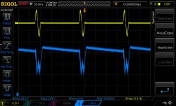
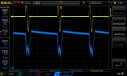
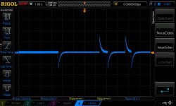
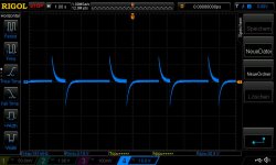
the scope probe is not on the smps . now its on the amps supply terminals
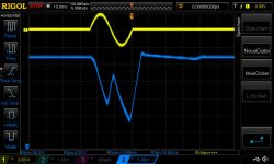
pictures with a CRC supply after the SMPS= 4x4700/35V -0,05R- 3x4700µF = about 33000µF
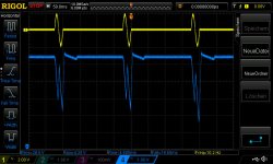
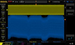
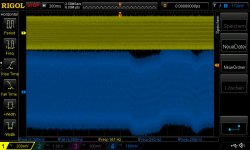
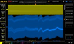
pic1+2 are with 40hz, 200ms 800mVrms burst
pic3+4 are with 40hz, 200ms 1300mVrms burst
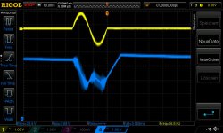
pic 5+6 are with 2x1000µF/50v low esr uhe nichicon 40hz, 200ms 800mVrms burst
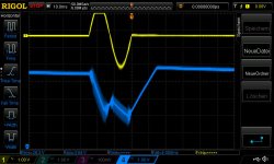
pic 7+8 are with 2x1000µF/50v low esr uhe nichicon 40hz, 200ms 1300mVrms burst
Last edited:
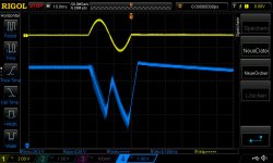
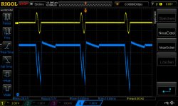

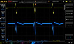
now the scope probes on the smps terminals with 2x1000µF caps
for comparison
for comparison
Attachments
-
 LRS150-24_40hz_4Routput_1Cycle_200msperiode_1300mVrms input burst_originamp_2x1000uF_2.jpg74.4 KB · Views: 73
 -
 LRS150-24_40hz_4Routput_1Cycle_200msperiode_1300mVrms input burst_originamp_2x1000uF_1.jpg77.7 KB · Views: 80
 -
 LRS150-24_40hz_4Routput_1Cycle_200msperiode_800mVrms input burst_originamp_2x1000uF_2.jpg76 KB · Views: 97
 -
 LRS150-24_40hz_4Routput_1Cycle_200msperiode_800mVrms input burst_originamp_2x1000uF_1.jpg79.2 KB · Views: 98
which figures get i if i use an traditional supply = transformer caps crc...???
better?
The visible audioband ripple mostly is a matter of caps impedance (ESR). Assuming 2A load audio ripple creates 40mV ripple across 20mOhm ESR for instance (assuming sufficient capacitance or high frequent audio signal).
Assuming traditional supply with 10.000uF may give you slightly lower audio ripple. But, being without regulation, you will notice the "smearing" of the way bigger 100Hz sawtooth rectifier ripple (1Vpp @ 1A load)
Hi Voltwide
Thanks you for your explanation. i really see the difference between the different of regulation and the burst reaction with the different cap versions.
for me 2 questions are open:
does burst with 800mVrms/1300mV be realistic during living room listening?
So the test is maybe "just" for tetsting the loop reaction.
what is the best solution during listening in a living room? with cap bank or without?
clear for me is that if you have to push for boom box or a large room you need some big SMPS (+caps?)
i checked the noise yesterday directly on the terminals of the cap. SMPS on amp on / amp on with signal 100mvrms. the different is nearly nothing...why? i
what is that singal?
during my testing i use a sweep 10Hz-35khz 150mVrms input at both inputs.
if i look with the scope diff. probe on the amp supply terminal AC coupled - i can see the frequency swwep in the noise singnal. what is that.....waht is that called?.... is that because the voltage regulation has a bad PSSR? (LM2575)
Last edited:
i checked the noise yesterday directly on the terminals of the cap. SMPS on amp on / amp on with signal 100mvrms. the different is nearly nothing...why? i
what is that singal?
during my testing i use a sweep 10Hz-35khz 150mVrms input at both inputs.
if i look with the scope diff. probe on the amp supply terminal AC coupled - i can see the frequency swwep in the noise singnal. what is that.....waht is that called?.... is that because the voltage regulation has a bad PSSR? (LM2575)
time to do the math:
What is output voltage and load impedance? -> calculate output current.
What is Power supply decoupling cap on amp PCB and its ESR? -> calculate voltage ripple to be expected
Besides - how can PSSR of LM2575 influence voltage ripple on power decoupling caps? I do not get this.
Generally excessive power decoupling caps are more often than not counterproductive when fed by smps.
A good amp design can handle a certain amount of supply ripple, and in reality you will not find any "ripple-free" supply.
So - where is your limit?
I assume that the levels shown by your plots are good enough to be of no significance for resulting sound quality.
Last edited:
time to do the math:
What is output voltage and load impedance? -> calculate output current.
What is Power supply decoupling cap on amp PCB and its ESR? -> calculate voltage ripple to be expected
Besides - how can PSSR of LM2575 influence voltage ripple on power decoupling caps? I do not get this.
........
Hi voltwide
thank you for your time...don´t forget i am a noob and i am asking strange questions😉
i thought that that regulator is bring some noise, ripple...what every to the rails...sorry...
i xcheck with the other boards / regulators...its a normal behavior...but pin 4 shows now nothing = =V before die..............and the board is dead..Sh@#&{}#} 😡
Hi
....before #541
yesterday i got my LM2575T-12 regulator and i but it in.
result:
opamaps are working with about 12V so its fine.
TPA chip is not working. the 2 LEDs fault and clip (at this board the LED are always on) are dark🙁
TPA 3255 pins
reset...87mV
FAULT 0,81mV
Clip otw..0,81
GVDD_cd 12,2 V
PVDD_X 28,7V
and same strange bumping as described before post 541!!.. i see the 1khz tone directly after the input cap is here but its bumping. that mean that you can see the signal..but in not regular periods i see the signal going up and down. so i set the time on my scope very long to see the bumping.
during changing the caps the pcb pads or off the pcb so this quality of traces are bad. i directly connect between the rca and solder pads with a smal cable...doesnt help......changing other caps are not solving this problem
yellow scope is input directly at rca
blue is the measurement after the first caps...
strange...?
Attachments
btw...
re checked after this strange things with an original board to see if my equipment has some error......no the measurments are ok.
could that be that the pcb traces are bad? because during i mod this board (withut cheking in original state) doing something strange..
re checked after this strange things with an original board to see if my equipment has some error......no the measurments are ok.
could that be that the pcb traces are bad? because during i mod this board (withut cheking in original state) doing something strange..
I understand that the TPA goes into fault mode. Assuming it is still ok there must be a reason for that. Probably some solder blob shorting an output line. Check all output pins separately for shorts to GND and PVDD respectively.btw...
could that be that the pcb traces are bad? because during i mod this board (withut cheking in original state) doing something strange..
Additionally do a diode test on relevant pins like bootstrap-supply.
That way you can 1:1 compare 2 boards and see quickly where the problems are.
That way you can 1:1 compare 2 boards and see quickly where the problems are.
thank you both expert🙂
....will see today....or...i like the board....but
....actually i am a bit pissed off the actual boards😡..the quality look bad...this is not acceptable for me. i never see such things
the version with just 1 regulator -blue with LM2575T-12 is making me crazy
....will see today....or...i like the board....but
....actually i am a bit pissed off the actual boards😡..the quality look bad...this is not acceptable for me. i never see such things
the version with just 1 regulator -blue with LM2575T-12 is making me crazy
I understand that the TPA goes into fault mode. Assuming it is still ok there must be a reason for that. Probably some solder blob shorting an output line. Check all output pins separately for shorts to GND and PVDD respectively.
pin to GND
OUT_D 6 ohms...
OUT_C 260ohms
OUT_B 350ohms
OUT_A 5 ohms
so its a short out_D + A
Additionally do a diode test on relevant pins like bootstrap-supply.
That way you can 1:1 compare 2 boards and see quickly where the problems are.
diode test 1
negative lead of the measurement tool (ohm meter set to diode test) on the pin - positive red lead to GND
good board shows 0,6V on BST_A,B, C, D
bad board shows on all 4 BST to GND 0V
diode test 2
red positive lead of the measurement tool (ohm meter set to diode test) on the pin - negative black lead to GND or V+
good shows OL on all 8 measurements
bad board shows at GND OL and on V+ 0,42V
chip dead?!?
...2nd board....pop on off noise...with mute switch
...second board makes troubles.....as i wrote...🙄😡
during testing my boards at the weekend between different power supply i use my nice board which i used for along time for 4R config, new opamp, new caps everything was fine.
the last time i want to use it i get surprisingly aloud pop noise....i use the switch and i never had this before....
any ideas? now i have the switch and during on/off i hear a loud pop! during mute the amp is still yueit so its working...but the pop is new😡
see pic 1+2 for left /right channel output.
Attachments
- Home
- Amplifiers
- Class D
- What is wrong with TPA3255?