Hi Chris, in my setup I'm using mordaunt short aviano 1 bookshelf speakers, I tried adding naim clone preamp 152xs. I also tested adding korg nutube headphone Amp as preamp.
Hi Chris, in my setup I'm using mordaunt short aviano 1 bookshelf speakers, I tried adding naim clone preamp 152xs. I also tested adding korg nutube headphone Amp as preamp.
fine....you like the sound of the amp?
i personly prefer a real stereo position of my speakers = e.g. the speakers are about 1meter away from the wall behind and its nothing inbetween the speakers. that means that i have room and space to do that.
try it and you will have more soundstage and more possibilites to compare amsp, pre amps and source.....etc..
...amp light V2
Hi
i am still working....😉
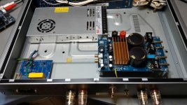
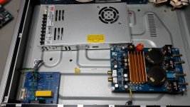
for my 2nd amp light project i use an old CD case from cambridge and i want to use the 350-36V for 8R configuration. space is enough in the housing..it is flat but it will work.
i want to use the AC plug and connection board in the left corner. the trani is just 40VA and 18V so no use for that amp😛.
Q:
pic 1- is is better to keep the distance for PSU to the amp short?
pic 2- is it better to keep the earth connection to the AC board short?
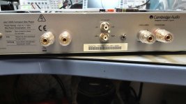
pic 3 is rear side. i use the toslink ans spdif holes for my speakers and adjust the other pair of speaker connectors to the left. the RCA hole is just fine to use my rca plugs. the mute/reset switch is just right to the RCA
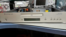
pic 4 is the front of the amp light 2
thank you
Hi
i am still working....😉
for my 2nd amp light project i use an old CD case from cambridge and i want to use the 350-36V for 8R configuration. space is enough in the housing..it is flat but it will work.
i want to use the AC plug and connection board in the left corner. the trani is just 40VA and 18V so no use for that amp😛.
Q:
pic 1- is is better to keep the distance for PSU to the amp short?
pic 2- is it better to keep the earth connection to the AC board short?
pic 3 is rear side. i use the toslink ans spdif holes for my speakers and adjust the other pair of speaker connectors to the left. the RCA hole is just fine to use my rca plugs. the mute/reset switch is just right to the RCA
pic 4 is the front of the amp light 2
thank you
Attachments
Hi
i am still working....😉
You are, Chris, and what an energy!
for my 2nd amp light project i use an old CD case from cambridge and i want to use the 350-36V for 8R configuration. space is enough in the housing..it is flat but it will work.
It looks good.
i want to use the AC plug and connection board in the left corner. the trani is just 40VA and 18V so no use for that amp😛.
You are right again.
Q:
pic 1- is is better to keep the distance for PSU to the amp short?
I would keep them well separated as long as you have good power line decoupling on the amplifier board. Too close and you may have noise from the SMPS radiated onto the amplifier board.
pic 2- is it better to keep the earth connection to the AC board short?
Not critical. The earth connection is mainly for safety. Even in Austria (with high-quality products like KTM, Rotax etc.......) you will find that earth connections are not always very low impedance. You may try to use it for reducing hum but the result will be varying.
Last edited:

24V (set 28V) vs 36V SMPS
Hi FF and others
Can you explain me the different of the SQ of more voltage of the amp?
i am asking because today my program was to clarify the sound difference of my SMPS. LRS 150-24 set up to approx 28V and the LRS 350-36 not adjusted higher because of my TI3251EVM board-............36V is enough.
as i can read the THD curve in the TI datasheet of 3255 but i am not working with 51V vs 53,5V at 4R or 8R but it is noticeable in the diagram.
my experience today was:
2 systems:
4R speakers with the correct boards: that means output filter 7µ/1µ(0,68µ) YJTPA3255 boards or my 3251EVM with my borrowed speakers = Disco M from my speakers friend.(excellent speakers)
8R speaker (sonus faber venere 1.5 with my YJ3255 board
the impedance and the sensitivity is different.....ok...but....
i tried since 5 hours a lot of songs boards and PSU´s changes...🙄😀
i recognized that my LRS150-24 is doing some very silent noise at the speakers..the ear is very near the chassis...the typical smps noisy sound
the LRS350-36 is silent
at 4R system i realized a small differenc between the SMPS...but maybe psycho acoustic...
but at 8R system its much bigger difference !!why?
could I have a technical, electrical, physically ....😀...explanation please😀
Last edited:
Hi FF and others
Can you explain me the different of the SQ of more voltage of the amp?
i am asking because today my program was to clarify the sound difference of my SMPS. LRS 150-24 set up to approx 28V and the LRS 350-36 not adjusted higher because of my TI3251EVM board-............36V is enough.
as i can read the THD curve in the TI datasheet of 3255 but i am not working with 51V vs 53,5V at 4R or 8R but it is noticeable in the diagram.
my experience today was:
2 systems:
4R speakers with the correct boards: that means output filter 7µ/1µ(0,68µ) YJTPA3255 boards or my 3251EVM with my borrowed speakers = Disco M from my speakers friend.(excellent speakers)
8R speaker (sonus faber venere 1.5 with my YJ3255 board
the impedance and the sensitivity is different.....ok...but....
i tried since 5 hours a lot of songs boards and PSU´s changes...🙄😀
i recognized that my LRS150-24 is doing some very silent noise at the speakers..the ear is very near the chassis...the typical smps noisy sound
the LRS350-36 is silent
at 4R system i realized a small differenc between the SMPS...but maybe psycho acoustic...
but at 8R system its much bigger difference !!why?
could I have a technical, electrical, physically ....😀...explanation please😀
Awaiting the reply from the big brains, I can give you a preliminary explanation.
Analog circuits change dynamic behavior with supply voltage.
Take an OP-AMP. It has got a varying THD performance depending on the supply voltage. Normally, supply voltages in the higher end leaves lower THD and in particular a much wider amplitude range with low THD. I have objected to the use of certain high-quality OP-AMPs (like LM4562) running at 12V in the input of the standard TPA3255 board (you know the right name, I just call it "the blue board"). With a 12 V supply, you simply do not use properly the potential of the OP-AMP.
Daniel recently gave a very elaborate reply about the use of TDA7293 with different supply voltages (and varying gain). Daniels conclusion was that you can alter the SQ importantly depending on which supply voltage you use and that the hunt for maximum "WATTS" is futile. Many chip-amps perform much better at lower supply voltages than those given as maximum. Tom once hinted that if you give an LM3886 maximum supply voltage the stability is reduced and the SQ negatively affected. I believe having read one of the really top-gurus stating that a problem in analog amplifiers is that the stability margin changes dynamically with the momentary output. It should relate to varying bias currents that causes varying dynamics (slew-rate) and changes stability which influences THD. THD we know has some influence on SQ.
For class D, with higher supply voltage you circulate higher currents in your output filter, increase core losses and influence THD. Skilled and trained people like you may notice such changes.
This was a lot of postulates. Take a Stroh-rum and have a good nights sleep. Tomorrow someone more skilled may invalidate all my statements.
In politics, a clever question (like yours) should always be countered with a counter-question (could leave the impression of the counter-question being intelligent even if the first question was not really understood): For 8 Ohm, was the SQ best with 24V or 36V supply?
Last edited:
Good Morning FF
first...on 8R i mean that the 36v sounds notable better.
Thank you for your statement. ... i read in other threads too. and thats nearly the same result i have in my mind.
the only thing is the Class D topic with the voltage at the OPAMP. if i remember after your changes at the input of the board voltwide wrote that it is not necessary to change the voltage because in his and doctors development the use the same architecture like in the TI boards. and the voltage range for this opamp is enough from 0V-12V because of the maximum input voltage of the TPA chips.
if you search at the datasheet of the TPA3255 chip with the key word "THD" you will find some interesting diagrams.
the first page shows that the THD is much better at 8R between 1Watt- 10Watt...and i guess that could be the change in SQ? isn´t it??
at figure 8-page 11 i found the output power of the different loads. but the difference between 28V vs 36V is not big. these 8V more give me more "dynamic" with 8V more then 8R...so its other way round😕
could that be that the adjusted 24V SMPS with 28V Volt is on its limit?? and maybe produce more noise?
thank you
wating for some other commments😉😀
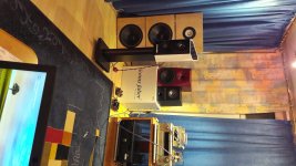
my room for listening...
Hi..here is some private....
here is my room under my terasse in the cellar. about 26m^2 but just 2,25m high. i have some negative room mods in lower frequency range. this is the reason i close mostly some bass reflex output with acoustic foam. but you can see my speakers are "free" standing as good as possible.
and NO! all speakers are not always in this corner😀...its just for the picture.😉
YES there are lot of thing standing around😀
have a nice weekend
ps... yes i have to clean the carpet ...😉
Attachments
Last edited:
ooops...the pic is turning....i try it 3 times but during uploading is swaping...... ... its made in the portrait format...sorry
Good Morning FF
first...on 8R i mean that the 36v sounds notable better.
Thank you for your statement. ... i read in other threads too. and thats nearly the same result i have in my mind.
the only thing is the Class D topic with the voltage at the OPAMP. if i remember after your changes at the input of the board voltwide wrote that it is not necessary to change the voltage because in his and doctors development the use the same architecture like in the TI boards. and the voltage range for this opamp is enough from 0V-12V because of the maximum input voltage of the TPA chips.
if you search at the datasheet of the TPA3255 chip with the key word "THD" you will find some interesting diagrams.
the first page shows that the THD is much better at 8R between 1Watt- 10Watt...and i guess that could be the change in SQ? isn´t it??
at figure 8-page 11 i found the output power of the different loads. but the difference between 28V vs 36V is not big. these 8V more give me more "dynamic" with 8V more then 8R...so its other way round😕
could that be that the adjusted 24V SMPS with 28V Volt is on its limit?? and maybe produce more noise?
thank you
wating for some other commments😉😀
Good morning, Chris
The small figure on page 1 shows the THD values for 8 Ohm loading to be better than for 4 Ohm loading. It is very often so. Slightly better SQ but less power. The figure does not show anything on change of supply voltage as such.
For the LM4562, I will refer to the Figures 3-14 of the datasheet. Here you find THD+N curves at varying supply voltage and loading. With Figure 6 as an example, you can see that the THD values at +/-2.5V is inferior to those above +/-12V.
Voltwide hardly makes any mistakes apart from settling in the gray Irish weather (however, taxes are low). His point, as I remember, was that 12V fully allows the TPA3255 to be operated to maximum output power with the gain of the TPA3255. This is a different consideration. It also depends on what OP-AMPs he is using. The XP16xx series seems to have very low THD at reduced supply voltages. You can also argue, why worry about the THD of the pre-amp stage when the power stage anyway has a higher THD?
Figure 8 (page 11) shows the output power you get with varying supply voltage and varying loading for a fixed THD value (close to the clipping point). Thus, with the same supply voltage you have more power in 4 Ohm than in 8 Ohm simply because the current is higher in 4 Ohm. That is trivial knowledge. You cannot reverse that conclusion to be that for any THD value you always have more power in a 4 Ohm load. It is valid only near the clipping level!
Your 24V supply (with 28V) may be close to a limit of the PWM modulation such that it has some dynamic regulation problems and accordingly a higher output noise level. I guess we are talking about electrical noise level, not acoustic noise level? Adjust it back to 22V-24V and see if the noise level is less.
I noticed from a photo you posted what nice gear (speakers in particular) you have. This explains why your listening tests are so credible. The only small problem seems to be that your house is build lying on the side and not, as it is tradition, upwards. The builders have to be careful how they turn the drawings.
Hi FF
the 4562 figure i remember...the same diagram is not existing for opa1602 or AD8599. i agree more voltage is working here.
XP16xx opamp.....hmm... i have just 2 types of soic opamps(opa1602, AD8599)an other input circuit is definitively something of my next planned tasks😉
@page 11 figure 8
this is what it makes me confusing, @4R....i though i have more "dynamic" power available with the difference of 8V this effects the SQ. but is is not. the better comes at 8R system with 8V more but less output available.
yes its electronic math and its simple. i understand😉
@smps
we had this discussion when i made my first hickup tests. and you explain me a nice method to check the loop reaction....its still not done..
the sound of the "peeeep" is herable in the speakers for the small smps closed to the HT speaker, the big one is quiet. the electronic noise level is not check with scope now...
i have to re check this!-
all boards have the same decoupling caps
doctors magic caps😉 -this silver Chemicon 661-EGPD630E242MM40H with this 5,22Amps @100kHz so the decoupling is the same - 4R- 8R....as i said much better then this original fat elna, sanwah 4700µF/63V..100V....old....whatever...fakes😡
@ picture-house
yes ....as i wrote listening is mandatory for me......
.yes....the austrians are strange guys 😀
hi again
@smps
we had this discussion when i made my first hickup tests. and you explain me a nice method to check the loop reaction....its still not done..
the sound of the "peeeep" is herable in the speakers for the small smps closed to the HT speaker, the big one is quiet. the electronic noise level is not check with scope now..
yesterday i did again compare of SQ between LRS24(28) and the LRS350-36
LRS150-24 is set to 28,69V and the LRS 350-36V is set to 34,94V
electrical noise checked....but the LRS24(28) looks better...so this could not be the reason
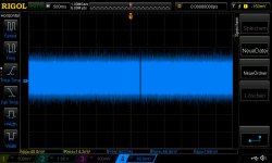
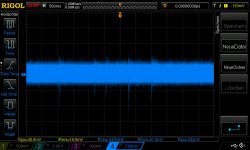
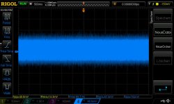
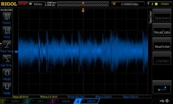
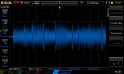
i made scope measurements during playing the same track and the same level of input voltage (checked with scope):
pic 1 is 24V during playing amp on
pic 2 is 24V during playing amp off
pic 3 is 36V during playing amp on
pic 4 is 36V during playing amp off
during playing same..at amp of 24v is better noise level....
nevertheless the sound on my venere 1.5 is noteble better with 36V smps...
will check today the "loop" reaction off both smps.....maxbe this gives me more clearance...😉
@smps
we had this discussion when i made my first hickup tests. and you explain me a nice method to check the loop reaction....its still not done..
the sound of the "peeeep" is herable in the speakers for the small smps closed to the HT speaker, the big one is quiet. the electronic noise level is not check with scope now..
yesterday i did again compare of SQ between LRS24(28) and the LRS350-36
LRS150-24 is set to 28,69V and the LRS 350-36V is set to 34,94V
electrical noise checked....but the LRS24(28) looks better...so this could not be the reason
i made scope measurements during playing the same track and the same level of input voltage (checked with scope):
pic 1 is 24V during playing amp on
pic 2 is 24V during playing amp off
pic 3 is 36V during playing amp on
pic 4 is 36V during playing amp off
during playing same..at amp of 24v is better noise level....
nevertheless the sound on my venere 1.5 is noteble better with 36V smps...
will check today the "loop" reaction off both smps.....maxbe this gives me more clearance...😉
Attachments
-
 LRS350-36_34,94 psu terminal during playing but amp off.jpg69.9 KB · Views: 454
 -
 LRS350-36_34,94 psu terminal during playing.jpg69.2 KB · Views: 451
 -
 LRS150-24 set to 28,7 psu terminal during playing but amp off.jpg70.2 KB · Views: 464
 -
 LRS150-24 set to 28,7 psu terminal during playing.jpg69.9 KB · Views: 474
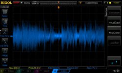
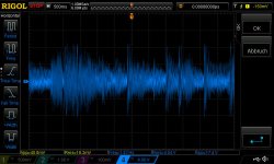
output was for both about 5-6V rms on the Rchannel during playing.
input about 230mV at the RCA connector Rch
pic 1 24V input
pic2 24V output
pic3 36V in
pic4 36V output
input about 230mV at the RCA connector Rch
pic 1 24V input
pic2 24V output
pic3 36V in
pic4 36V output
Attachments
This thread is long to read fully. I want to know the practical rms output one can achieve using TPA3255 and maximum voltage it can handle to work simultaneous in real life application. Is the 600W mark really can be achieved? Also what is the continuos output one can achieve without any issues?
This thread is long to read fully. I want to know the practical rms output one can achieve using TPA3255 and maximum voltage it can handle to work simultaneous in real life application. Is the 600W mark really can be achieved? Also what is the continuos output one can achieve without any issues?
Provided your speaker has 2 Ohms impedance, the pcb-layout is perfect, sufficient power and sufficient cooling is provided, you may reach this mark as shown in the data sheet.
But in that case you would be driving this tiny thingy definitely at the edge.
Keep in mind that amps for music reproduction are not specified for continuous output power - simply because regular audio does not require this.
I can say that loading the TPA3255 with 8 Ohms in PBTL configuration about 100W continuous power output is realistic without any issues using a small heatsink. Did not try more.
Last edited:
This thread is long to read fully. I want to know the practical rms output one can achieve using TPA3255 and maximum voltage it can handle to work simultaneous in real life application. Is the 600W mark really can be achieved? Also what is the continuos output one can achieve without any issues?
Hi
no . with this YJTPA3255 board this requested power is not achievable. many pages before a made a test with about 40W continuously without fan...after 42minutes the heatsink get 102°C nd the amp switch luckly off.......
With TPA3255EVM by TI much more....As voltwide wrote...
- Home
- Amplifiers
- Class D
- What is wrong with TPA3255?