After reading all this I think there is a good case for using headphones.
C.M
Or fullrange speakers.
True. But JBL is one of the BIG BOYS. What are they trying to say by having that diagram.
JBL is not big anymore, they sell a lot of crap today.
Unlike in the glory days of old.
There is no point talking about a diagram that basically says nothing.
But if you want to...
What do you think JBL wants to tell us?
These are the Impulse Responses of the woofer with the LP filter (yellow) and the tweeter with the HP filter (green). Both peaks coincide at the same point, does that mean the sound from the tweeter and the woofer reach the mic at the same time?
Those IRs look plain single channel measurements without common time reference because peaks are exactly at 0 us. If really so, REW has manipulated timing and curves are worthless for conclusions about timing difference.
Or fullrange speakers.
One of the reasons I use widebands (I can't find fullrange speakers)
One of the reasons I use widebands (I can't find fullrange speakers)
😀
What`s the difference?
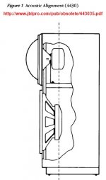
JBL 4430 Figure 1 Acoustic alignment: http://www.jblpro.com/pub/obsolete/443035.pdf
Design info: https://pearl-hifi.com/06_Lit_Archi...her_Publications/Improvements_Monitor_LSs.pdf
Design info: https://pearl-hifi.com/06_Lit_Archi...her_Publications/Improvements_Monitor_LSs.pdf
I am always puzzled, when I see a diagram, where driver magnets (motors) are aligned, like in the old JBL brochure. I have the belief that sound propagates from the driver diaphragm instead...
This whole issue is vaque, it depends on so many variables that are interacting. I am fan of symmetric slopes and nice summation 1-2 octaves past xo. This is difficult enough because of response irregularities on- and off-axis etc. After long time listening I prefer LR2 over LR4 in my AINOgradient 4-ways, kind of more natural sound for piano etc..
This whole issue is vaque, it depends on so many variables that are interacting. I am fan of symmetric slopes and nice summation 1-2 octaves past xo. This is difficult enough because of response irregularities on- and off-axis etc. After long time listening I prefer LR2 over LR4 in my AINOgradient 4-ways, kind of more natural sound for piano etc..
I have the belief that sound propagates from the driver diaphragm instead...
Of course.
I am always puzzled, when I see a diagram, where driver magnets (motors) are aligned, like in the old JBL brochure. I have the belief that sound propagates from the driver diaphragm instead...
This whole issue is vaque, it depends on so many variables that are interacting. I am fan of symmetric slopes and nice summation 1-2 octaves past xo. This is difficult enough because of response irregularities on- and off-axis etc. After long time listening I prefer LR2 over LR4 in my AINOgradient 4-ways, kind of more natural sound for piano etc..
That picture seems pretty clear to me. The axis we see originating between horn and woofer is their "design axis". The half sphere shapes is the sound originating from the respective drivers. They also indicate the angles at which the horn and woofer go out of phase, both above and below the design axis.
This is what I've mentioned a couple of times, with a quick sketch. Where do you want your drivers to be "in phase". Usual answer: at the crossover frequency. My answer would be: at the crossover frequency as observed from the listening spot.
That's what JBL shows here, where that listening spot should be, at least along which axis to expect it. Their text speaks about a symmetrical 12 dB/oct crossover.
Choosing the design axis to be between horn and woofer ensures the direction of that design axis. If they would have picked "tweeter level" as the design axis things would look different in this picture. See the note why the design axis rises slightly.
Last edited:

These are the Impulse Responses of the woofer with the LP filter (yellow) and the tweeter with the HP filter (green).
Hi mark
I don't have any DSP. The only delays I have are from analog crossovers for pa use. But those delays are for woofers. No provision for tweeter delay because in pa speakers, the compression driver is usually behind the woofer.
What makes you doubt your phase and time alignment based on those two IR plots? Your waterfall plot, the sum and dip at the listening spot as presented way earlier all confirm your alignment at the measured spot of ~0.9 m.
The waterfall plot, showing the hand off between tweeter and woofer:

Sum at the design spot:

Dip if we invert one driver:

So why doubt it now?
However your design axis was at tweeter level. Meaning the "line", where this particular alignment will hold true, will rise as distance to the speaker increases.
If we look at the IR of the tweeter alone, and compare it to the total system IR, we basically see the same trends, the only difference being the bass energy is added (in sync). The tweeter (with filter) has it's top end inverted (negative spike) and phase rotates to be in line with the woofer at the crossover frequency.
The question is: is this what you wanted? Another question is, how does it do or hold up off axis? Do you want to place the enclosure lower to be in phase at larger distances? And what is your proposed listening distance?
An IR is a representative of all the energy as measured. But without digging deeper into it, how will you know what frequency you're actually looking at?
I see your opinion and point on that. I often listen on the headphones to check a film soundtrack then go back listening on the loudspeakers to see what I may or might have overlooked?After reading all this I think there is a good case for using headphones.
C.M
Headphones face inwards at our ears. Okay so I'm stating the obvious. Loudspeakers we don't often place them side to side of our head/ears they are often placed in front with L/R toed inwards.
The bass seems more enclosed around the ears due to the closed headphones being cupped around the ears. The sense of room or the sense of it yeah sounds like a treated room.
I guess I could with a multi-channel mixer feed the DCX2496 outputs to a mixer and blend all the LF HF together and fiddle with delay time settings to see how that sounds? Yeah I could do that if I had new cheap multi-audio mixer.
Use the line inputs for say
Left LF HF
Centre LF HF
Right LF HF
Then use the stereo line output to the headphones.
Blend all the levels together and in phase then mess around with delay settings.
Thanks JBL4645,
that is exactly what I complained. In the original JBL paper the line goes through magnets/coils, not membranes that make sound.
This kind of pictures we see a lot and they are wrong, considering physical/acoustical time alignment! In most cases yes they will set acoustic centres well too, but the line is in wrong place anywy!
Attachments
Last edited:
Michael
For some reason, what works best for me for time arrival measurements is HolmImpulse.
You may want to check this:
The Subwoofer DIY Page v1.1 - Time Alignment using HolmImpulse
For some reason, what works best for me for time arrival measurements is HolmImpulse.
You may want to check this:
The Subwoofer DIY Page v1.1 - Time Alignment using HolmImpulse
the speed of sound is finite.I am always puzzled, when I see a diagram, where driver magnets (motors) are aligned, like in the old JBL brochure. I have the belief that sound propagates from the driver diaphragm instead...
.............
It takes time for sound to travel through a medium/material.
The speed of sound in air is normally understood by us. One must also recognise that solids and liquids also have their respective speed for a sound wave.
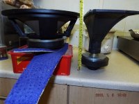
The cone and the former each have their respective sound travel times.
One must add up all the travel times from the initiation at the voice till we hear that sound at our ears.
mark
The easiest route is of course to use a digital delay. Find one that can adjust at 0.01ms. Better still, at 0.001ms.
What say you.
Hi Michael, I would highly recommend you get something like a miniDSP to adjust the delay, like maybe the $205 2x4HD miniDSP in a BOX : miniDSP 2x4 HD
It runs at 96kHZ so you can adjust delay by 0.01ms.
(That's where the +/- 0.02ms comes from in REW btw...1 sample at 48k.)
It makes an outstanding learning tool if nothing else...and even has a little FIR capability.
Time alignment changes every single frequency in the band by the same amount.
Phase alignment changes every single frequency by different amounts, depending on the angle and frequency.
Sorry but, no.
//
- Status
- Not open for further replies.
- Home
- Loudspeakers
- Multi-Way
- What is Time-Alignment