LMAOWhat's all this talk of dipoles? 😉
And again 😉BTW, no baffle would be best 🙂
Hi Scott,
I'm unsure how to go about figuring the acoustical load and just 'flying by the pants' approach, if you get my meaning...!
Trying to assess the rear acoustical load rather than model the geometry/profile is further complicated by the diffraction of the pressure waves around the driver itself, assuming negligible interference from the driver frame and spider/magnet surface (not sure of this either) so the acoustical load can maybe approximated to the inside shape of the outer profile and can be further modified by vertical deflection like the 'horn lens'.
However, as the top edge of the baffle is 'open to front wave interference effects and the bottom surface, even modified by a sloping/curved panel to reduce reflections will present uneven complications that 'juha' has mentioned, or as you have mentioned, a possible 'horn load'.
Perhaps this curved baffle now can be tapered at the top/bottom like the Caintuck Audio "barrel shaped" baffles to extend the benefits into the high treble area for the wide-range drivers and include the off-center positioning too (unequal sides)?
I have played around with rear exponential loading by deflection panels but it seems to produce more problems than potential solutions probably by the paucity of theoretical modelling that seems to be lost to time - I do remember some loading experiments with elliptical rear loading impedance but much of this culminated in the tapered resistance method employed by the B & W midrange designs about that time.
I think the Danny Ritchie explanation about the effects of the 110 degree angled L panel design on freq response makes good practical sense to acoustically 'even-out' the OB speaker response (not a small achievement in my view at all!), and the 'cut-out' of the side panel for the treble balance is right 'outside the box' thinking, IMO.
As juha mentioned, there are reservations and limitations to all this but the potential is there and maybe adding a curved baffle surface with further 'irregular' edge options can extend the benefits...
I think Sigmund's limited baffle with extensive dsp modelling as per the LX521 illustrates the benefits of minimum baffle surface but I'm a bit hesitant about the extensive signal modifications by dsp (dislike the 'sound' of the 'mini dsp product) but I have high hopes for Nelsons recent analogue version for the 2 way version that might help reduce baffle limitations too.
Simple tools for simple minds - that fits very well here!
Thanks for the links to that program and juha's input too - always room for better understanding
This is either very wrong or I have still not understood diffraction from baffle edge
Gedlee said:FYI, if a speaker were placed in the hole of a donut (mathematically a toroid), it would not have any edge diffraction. I told this to Linkwitz many years ago, but he was not interested. Always wanted to try it, but hey, there are lots of things one could "try"!
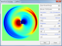
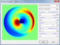
What is the name of the simulation SW and where can I find these used by Allen and Juha (I see Wavefront Simulator in some pictures but can't find any such SW on internet)?
I found some other SW that could perhaps be used to simulate baffle stuff?
wavefront download | SourceForge.net
AcouSTO download | SourceForge.net
I found some other SW that could perhaps be used to simulate baffle stuff?
wavefront download | SourceForge.net
AcouSTO download | SourceForge.net
Last edited:
This is the one I've been using - Ripple Tank Simulation
This is hornresp.exe - Hornresp
Juhazi is using Edge
This is hornresp.exe - Hornresp
Juhazi is using Edge
Thanks Allan, I'd forgotten about this - now how to make a BIG toroid, eh?
I have some pieces of scrap 3" thick styrene from building sites that I 'hot-knife' cut for diffusors - that could work, yes? I doubt that the surface would be critical but maybe seal and paint?
I wonder if I started with an 18mm ply layer for driver mounting then simply add layers of 3" styrene and cut down to shape with a 'hot-knife' (similar to cutting diffusors) then seal the outer surface - oops, it's all outer surface, yes!
This reminds me of something but I can't remember.
If the internal toroid diameter was to match the 8" driver dia (my Wild Burro 8" FR Betsy drivers, for example with a 208mm dia) with an 18mm plywood layer for driver mounting, what would be the outer dia for an Fs about 150Hz?
Is there someway to figure this out? Perimeter estimates (hence outer dia) converted from baffle size calculations, or double the baffle size, etc ?
Quite an interesting idea, eh! Surely, someone has tried this before?
Thanks Rob for your post on the link of Allen's - inner tube + fiberglass coating or child's swimming 'floatie"
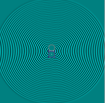
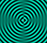
could you do a couple more at 100Hz and 5kHz please?
1000 hertz is the maximum allowable frequency for the 135 x 135 resolution and 2.5 cm element size used in the simulations. Higher frequencies would generate inaccurate results due to aliasing effects.
Attachments

Some relevant chat went this way - This is either very wrong or I have still not understood diffraction from baffle edge
I think you must have been "lucky" 😉 This shouldn't affect the nulls above the dipole peak other than shifting them in frequency? It is an interesting idea though, could reduce the degree of nulling similar to naked driverThis is something Earl Geddes suggested some time ago.
It's interesting, this quick view may not be comprehensive, but the on axis nulls aren't appearing.
Last edited:
Perhaps this curved baffle now can be tapered at the top/bottom like the Caintuck Audio "barrel shaped" baffles to extend the benefits into the high treble area for the wide-range drivers and include the off-center positioning too (unequal sides)?
Or curve the wings and keep the baffle narrow? Asymmetric U frame open baffle?
1000 hertz is the maximum allowable frequency for the 135 x 135 resolution and 2.5 cm element size used in the simulations. Higher frequencies would generate inaccurate results due to aliasing effects.
Thanks David
You name the test and we'll do it, but I'm betting it isn't like that. The baffle edges are specific locations where the diffraction occurs. The toroid spreads the diffraction in time and space. The effects are bound to be less specific, as well as less pronounced.I think you must have been "lucky" 😉 This shouldn't affect the nulls above the dipole peak other than shifting them in frequency?
Attachments
Yes, like a naked driver of continuously varying diameter or fuzzy edged like a felt OB, there is a thread about that, it worked well. The reduction in the 90degree null could be why SL wasn't interested.The baffle edges are specific locations where the diffraction occurs. The toroid spreads the diffraction in time and space. The effects are bound to be less specific, as well as less pronounced.
It is an interesting idea though, could reduce the degree of nulling similar to naked driver
Last edited:
I thought the nulls were even better. They are so wide. They don't have to be total nulls. Eg. -20dB over a wide angle might be quite beneficial and I'll take that over -40dB over 10 degrees on any day. Anyway, they're so similar to the naked driver everyone keeps talking about.
Also note that the toroids have less HOM than the ideal naked driver, and a real shape is much worse, as is the efficiency of the naked version.
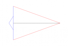
Image 1, point source on toroid at a rather high frequency.
image 2, Ideal naked driver
image 3, triangular driver shape, naked
Also note that the toroids have less HOM than the ideal naked driver, and a real shape is much worse, as is the efficiency of the naked version.
Image 1, point source on toroid at a rather high frequency.
image 2, Ideal naked driver
image 3, triangular driver shape, naked
Attachments


It's a dipole horn! I remember someone describing a dipole as a flattened horn(?). Can you remove the horn effect so the edge of the baffle is rounded at the sides only, also do similar with the L shape please? I'm going to have a play with that simulator, I only have a chromebook so limited to what I can do.
Horn loading has nothing to do with it, and a waveguide is more of a baffle, with thought put into it.
One downside to the naked driver is it's very low efficiency. The standard baffle improves this by delaying the meeting of the two sides, but when it happens the result is distinct.
PS I'm not sure if this is what you meant.
One downside to the naked driver is it's very low efficiency. The standard baffle improves this by delaying the meeting of the two sides, but when it happens the result is distinct.
PS I'm not sure if this is what you meant.
Attachments

Yes thanks, I wanted to see if the effect on the nulls was consistent. I also wondered if rounding would have much effect on the dips to the rear of the L frame, I still doubt this matters much, if at all, and some of it is interference of reflections probably.
- Home
- Loudspeakers
- Multi-Way
- What is the polar response of "L-frame" OB speakers