What would a baffle 12" wide with one 3" wing and one 12" (and 15" for comparison) look like please?
What is the driver diameter?
There would also be a 3" "wing" on top the same distance from the driver as the sides, I don't know what difference that would make or if it can be simulated.
Hornresp wavefront simulator models are two-dimensional only.
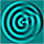
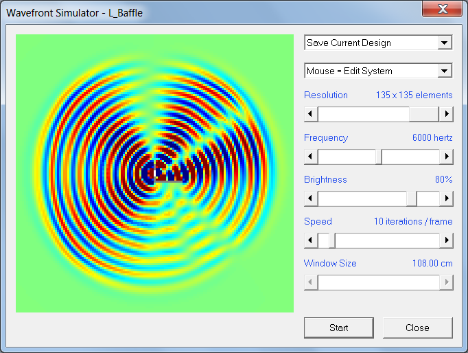
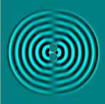
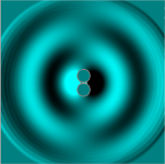
This is the straight baffle. Performance remains to a higher frequency, presumably due to the lack of baffle clutter. The nulls are consistent.
The higher order modes are also relativly simple, which has it's own story to tell.
Hi, how to interpret the simulation pictures, where are the sound pressure maxima, and what does "null" mean in this context, same as sound pressure minima, ie. cancelation?
Hornresp shows one frequency at the time, there are sliders to change parameters.
In graphs color and density tell pressure. To me it looks like "diluted" color up to background green is minima in this graph
In graphs color and density tell pressure. To me it looks like "diluted" color up to background green is minima in this graph
What is the driver diameter?
4", it's the Jordan Eikona in a VTL cabinet with removable back panel http://www.ejjordan.co.uk/PDFs/Eikona_2_VTL.pdf hence the 3" wing 🙂
I built it with removable back with the intention of experimenting with OB, see post #35.
where are the sound pressure maxima, and what does "null" mean in this context
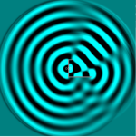
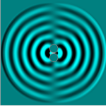
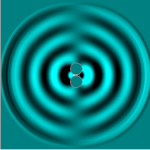
In the Hornresp wavefront simulator, maximum positive pressure (compression) is red, maximum negative pressure (rarefaction) is blue, and zero pressure (null) is light green (the background colour).
4", it's the Jordan Eikona
Attachments

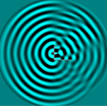
Thanks David that's very helpful, could you do a couple more at 100Hz and 5kHz please? There's still quite a decent dip on the long wing side.
In the Hornresp wavefront simulator, maximum positive pressure (compression) is red, maximum negative pressure (rarefaction) is blue, and zero pressure (null) is light green (the background colour).
Yes, I was thinking of nulling when color "dilutes" ie. amplitude gets very low.
I don't remeber if window pixel count is fixed, a larger window/zooming would help to see what happens at high freq.
Graph is easy to look at and understand, but not so easy to describe in words!
Since the idea of wings is to effectively widen the baffle without widening the baffle I think it would be better to keep it as narrow as possible. I may not be understanding you correctly, curved in what way exactly?
To have the narrow front panel (driver diameter width) and the side wings are curved so there's no 'front baffle edge' to produce diffraction response anomalies - no abrupt surface change in direction, just smooth continuation of (say) a parabolic function.
There have been quite a few OB designs with curved baffles over the years so just following on with that.
I expect it to also effect the acoustical loading at the rear too, but that's from an old idea from a tall curved OB design that added directional vanes at the back - a Swedish design, I vaguely recollect.
We played around with a similar idea to widen the 'sweet-spot' on the planer drivers like the Maggies - unsuccessfully, unfortunately.
Thanks both David and Juha, yes I understood that too where the blue and red "waves" are less prominent is the region with lower pressure variation.
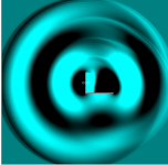
It seems to me when one goes relatively high up in frequency for instance with the L shape it starts to behave like a horn in one direction, and the edges where the walls ends produces diffraction artifacts which adds up to more complex polar pattern in some parts although it seems to be more a problem with the backward going waves...?
It seems to me when one goes relatively high up in frequency for instance with the L shape it starts to behave like a horn in one direction, and the edges where the walls ends produces diffraction artifacts which adds up to more complex polar pattern in some parts although it seems to be more a problem with the backward going waves...?
Last edited:
Curved or sidewing baffle backside is a horn and has different directivty and even horn modes - above dipole peak. Period. For full-range dipole one must use multiway system with varying baffle width!
Here Edge sim with a flat baffle, driver asymmetrically and of-axis to left and right. I would not even try to optimize it to play above dipole peak!
Here Edge sim with a flat baffle, driver asymmetrically and of-axis to left and right. I would not even try to optimize it to play above dipole peak!
Attachments
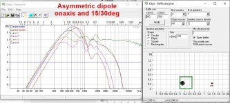
That edge interferene peak happens with closed boxes as well, but this was about open L baffle, which naturally has dipole characteristics.
I'm pleasantly surprised at how it looks to the front and sides. The rear, of course, has a combination of things happening. However since the rear radiation should ideally be diffused I don't think the horn like behaviour would be a problem so long as there aren't any major resonances. Is this calculator useful? Cavity Resonance
This is something Earl Geddes suggested some time ago.What happens if you use a narrow front with curved 'side-wings'?
It's interesting, this quick view may not be comprehensive, but the on axis nulls aren't appearing.
Attachments
- Home
- Loudspeakers
- Multi-Way
- What is the polar response of "L-frame" OB speakers