With a blocking cap you lose nothing.
Actually with a 22 uF (Figure 7.18 SSD) you give back about 720 Ohms at 10 Hz which is more than the MM cart's DCR. The model in figure 7.19 doesn't include Xc.
That's the argument I suppose for not having a Cin and allowing Ib to flow.
I can show you a phantom-tolerant mic preamp without input coupling caps if you'd like...
Last edited:
Actually with a 22 uF (Figure 7.18 SSD) you give back about 720 Ohms at 10 Hz which is more than the MM cart's DCR. The model in figure 7.19 doesn't include Xc.
That's the argument I suppose for not having a Cin and allowing Ib to flow.
Not a good one. That 720 Ohms is reactance and not resistance, and therefore does not generate Johnson noise.
Always happy to look at circuitry!I can show you a phantom-tolerant mic preamp without input coupling caps if you'd like...
@ DouglasSelf
Hi, it took a while for you to respond 😉
My phono preamp with OP27's was tested my Les Sage of Sage Audio, & it's SNR was 74db re 5mV. I never heard any hiss, or hum, @ high levels inbetween changing records ! I was using high effeciency speakers though. Anyway, it sounded, & sounds, excellent in EVERY regard. Riaa is passive hf & active lf.
@ DouglasSelf
Hi, it took a while for you to respond 😉
My phono preamp with OP27's was tested my Les Sage of Sage Audio, & it's SNR was 74db re 5mV.
Weighted or unweighted?
Not a good one. That 720 Ohms is reactance and not resistance, and therefore does not generate Johnson noise.
Thank you Douglas. That is correct. It does not generate Johnson noise. But I think you will agree that it appears in series with the source impedance.
Unfortunately signals flow both way in this circuit. The consideration is current noise flowing outward.
From the op amp's perspective looking "out" into the source, the capacitor is in series with the cart's source impedance. Noise current from the op amp input develops across the cart and Xc. At LF, the impedance of the cart approaches its Rdc while at the same time Xc rises.
For a given LF noise current, wire will be quieter than a capacitor that is increasing, in the case of a 22 uF and a 600Ω cart perhaps doubling, the effective source impedance. The increase in 1/f noise is then made far worse by the +20 dB LF boost of RIAA EQ.
For bipolar input preamps, keeping Xc small, or making it 0Ω, is the key to managing current noise.
I see this common mistake when sizing input capacitors for microphone preamplifiers. The capacitors are made too small and LF noise performance is compromised.
A proof-of concept prototype for an input-capacitorless mic pre has been "Protoboarded" through several iterations since 2007. The preamp uses flying supply rails to bracket the input device supply lines around the DC common mode voltage of the microphone. This allows the coupling capacitors to be moved from the front-end to the output of the preamp. I haven't worked on it in awhile and would now change the servo injection technique so it remains a work in progress. The last complete iteration is here for your amusement:
Pro Audio Design Forum • View topic - New: A Direct-Coupled Input-Capacitorless Active Mic Preamp
On my next visit here I hope to detail a simple way to encode/decode MS and show the Allpass-corrected filter used to perfrom Elliptic EQ and warp reduction.
Last edited:
Weighted or unweighted?
Simulating with LTSpice shows that both is possible.
When measuring noise from 20Hz to 20Khz, ref 5mV and using the typical values of the Op27 with:
3nV/rtHz and 0.4pA/rtHz, with resp. corner frequencies at 8Hz and 30Hz.
Input shorted:
Unweighted 82.7 dB
Weighted 87.1 dBA
Cart Connected assuming 500mH in series with 600 Ohm:
Unweighted 76.6 dB
Weighted 79.4 dBA
So when properly designed, the measured 74 dB could very well be unweighted with the Cart connected.
Not bad at all.
Hans
How did you allow for the noise from the bias cancellation system?
How did you allow for the noise from the bias cancellation system?
Voltage and current noise contribution from the bias cancellation system were supposed to be included in the noise figures as published by AD.
If this were not the case, noise figures would be very deceptive.
Hans
Voltage and current noise contribution from the bias cancellation system were supposed to be included in the noise figures as published by AD.
If this were not the case, noise figures would be very deceptive.
Hans
How can that be so? The way that the bias cancellation currents turn into voltages depends on the impedance at each opamp input. If you look at the last three plots in the OP27 data sheet, you can see how the noise is degraded when these impedances are not the same. How could that be incorporated into single voltage & current noise density figures?
How can that be so? The way that the bias cancellation currents turn into voltages depends on the impedance at each opamp input. If you look at the last three plots in the OP27 data sheet, you can see how the noise is degraded when these impedances are not the same. How could that be incorporated into single voltage & current noise density figures?
I see absolutely nothing special looking at those noise plots.
I will use my LTSpice model with the same resistor values tomorrow and I'm sure the outcome will be identical.
Two resistors produce more noise than just one, and that's what you see.
Hans
I disagree. Noise is greater for unmatched input impedancesI see absolutely nothing special looking at those noise plots.
And does this model include bias cancellation noise?I will use my LTSpice model with the same resistor values tomorrow and I'm sure the outcome will be identical.
Last edited:
It's been a Long time since i looked at the test specs for my phono stage, that Les Sage kindly did for me. My memory said 74db SNR re 5mV, but on digging out the specs i discovered it's actually 72db SNR re 2.5mV. Which = 78db SNR re 5mV = Nice ! He said the test was IHF input short circuited & CCIR weighted.
I was under the impression that, unequal resistance/impedance caused THD to increase, not noise ? Granted that higher resistance/impedance does increase noise though.
@ Hans Polak & mediatechnology
Thanx for the info 🙂
Originally Posted by DouglasSelf
Noise is greater for unmatched input impedances
I was under the impression that, unequal resistance/impedance caused THD to increase, not noise ? Granted that higher resistance/impedance does increase noise though.
@ Hans Polak & mediatechnology
Thanx for the info 🙂
@ Douglas Self: I think the issue is whether the input current noise of the opamp is 'the' input current noise which includes whatever mechanism there is to generate it. Bias current cancellation might be one of these mechanisms, but there should not be any reason to single it out and use as a separate noise source.
Or am I missing something here?
Jan
Or am I missing something here?
Jan
Seems a mechanical solution is best for damping rez. Then, add a HP filter if still needed. If that is done... pls measure the group-delay as well.
THx-RNMarsh
THx-RNMarsh
This is an OP27 functional schematic:

Q6 provides bias current correction equally (or almost so) to both inputs.
The noise currents induced by Q6's collectors are highly correlated.
When the input source impedances are equal, the correlated noise is rejected by the common mode rejection of the OP27.
When the source impedances are unequal there is common mode to differential conversion.
It would appear that a shorted input test would be kind to an OP27. There would be little to no impedance at the non-inverting input and little to no noise contribution from Q6. The inverting input however would see an impedance much greater than 0Ω.
With a typical non-inverting RIAA stage the inverting input would see the RIAA FB network in parallel with the gain-setting resistor and DC blocking cap. Using the OP27's datasheet (figure 41) as an example the inverting input sees about 100Ω to ground. http://www.analog.com/media/en/technical-documentation/data-sheets/OP27.pdf
When the input is open circuit (also using figure 41) the noninverting input sees 47K5||150pF but the inverting input sees 100Ω an imbalance of 475:1.
For balanced inputs it's possible to use a trick I call "T-bias" where the input bias resistors (or transducer termination resistors) common to a single larger value "common mode" resistor to ground. I mention it here because it illustrates the advantages to forcing uncorrelated noise sources into common mode. A majority of the noise voltage from uncorrelated current noise develops in common mode (as well as DC bias current offset) where it can be rejected. I had this added to the THAT1510 datasheet years ago. http://www.thatcorp.com/datashts/THAT_1510-1512_Datasheet.pdf I first recall seeing it in the SSL82E149 mic input. http://www.ka-electronics.com/images/SSL/ssl_82E149.pdf T-bias works only for balanced circuits. It's advantage is reduced coupling cap matching owing to having a higher CM impedance than differential.
Shorted input tests can be very, very misleading.
Last edited:
I see absolutely nothing special looking at those noise plots.
I will use my LTSpice model with the same resistor values tomorrow and I'm sure the outcome will be identical.
Two resistors produce more noise than just one, and that's what you see.
Hans
You guys doth protest too much, Ib cancellation adds 3dB (at most) to the current noise that's just physics. That is 1pA per root Hz becomes 1.4pA prt rt Hz, these numbers are all on the datasheets and even reflected in the macro models. If you simulate you need to use a full model of a cartridge and the termination, on the bench use an old cartridge with the stylus removed. It takes a while for the Ib noise and response peaking to overcome the the thermal noise of the real part of the cartridge impedance. In fact with MI like a Grado it never does to a meaningful extent. The bottom line is that there is no general case all carts are different.
BTW I've seen schematics of John Curls designs (aimed firmly at those who spend $2000+ on cartridges) and have never seen a coupling cap.
Last edited:
Q6 provides bias current correction equally (or almost so) to both inputs.
The noise currents induced by Q6's collectors are highly correlated.
Sorry that's not as true as folks think. Just because a split collector PNP is super-integrated does not mean carrier emission is correlated they are still individual events and partition noise messes things up. I have measured more like 20%.
Seems a mechanical solution is best for damping rez. Then, add a HP filter if still needed. If that is done... pls measure the group-delay as well.
THx-RNMarsh
Agreed. For a BW response, the simulations show ~70mS GD at 20Hz and it falls below 20mS at freqs above 30Hz.
How did this thread go from a conventional filter solution to arguing about Ib noise and proper termination/coupling for cartridges?
Attachments
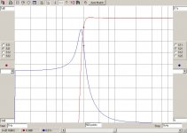
Agreed. For a BW response, the simulations show ~70mS GD at 20Hz and it falls below 20mS at freqs above 30Hz.
How did this thread go from a conventional filter solution to arguing about Ib noise and proper termination/coupling for cartridges?
Was this measured with a Bode 100?
Jan
- Status
- Not open for further replies.
- Home
- Source & Line
- Analogue Source
- What is the ideal conventional rumble filter?- Douglas Self