8 pole BW 18Hz HPF
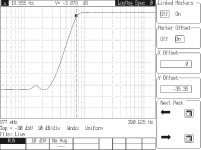
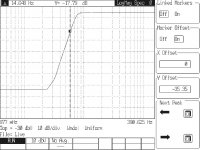
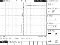
While the general consensus seems to be focused on eliminating the cause of subsonic oscillations at the cartridge/tonearm interface (which I agree is the best remedy), I've experienced this problem first hand after changing cartridges and have (so far) been unable to cure it. Assuming I can find a mechanical solution, I still wanted to try a conventional subsonic filter in the vein of the OP. I first proposed this circuit in post # 154, but have refined it somewhat by reducing the caps to reasonable values (220n), and was able to achieve excellent results using E24 5% resistors and 5% Wima polypropylene caps.
I breadboarded the design and the measured results closely correlate with the simulations:
-48dB at 10Hz
-3dB at 18 Hz
-1dB at 20Hz
-0.1dB at 24Hz
I sent the Gerber files to OshPark and should have a working prototype in a couple of weeks. If there is interest, I can share the PCB via OshPark and make the schematic and BOM available as a DIY project.
Attachments
-
 18Hz HPF 3dB.jpg303.2 KB · Views: 324
 -
 18Hz HPF at 15Hz.jpg312.2 KB · Views: 323
 -
 18Hz HPF at 10Hz.jpg301.8 KB · Views: 316
 -
 18Hz HPF at 6Hz.jpg312.3 KB · Views: 318
 -
 18Hz HPF at 20Hz 2dB-Div.jpg289 KB · Views: 313
 -
 18Hz HPF at 24Hz 2dB-Div.jpg305.7 KB · Views: 101
 -
 18Hz HPF Simulation.jpg102.8 KB · Views: 119
@ mediatechnology et al
Nice links 🙂
I don't know why the OP27 or OP2227 are often overlooked ? From the OP27's data sheet
Plus lots of other Very good specs !
My phono stage i designed & built nearly 30 years ago with OP27's is hard to beat !
Because the OP27 is as noisy as hell in MM applications, because of its bias-current cancellation circuitry. The OP2227 also has this, and while I have not measured it myself I can so no reason why it should not suffer the same trouble.
With reference to the discussion on bias currents, I am at a loss to understand why anyone would even consider putting DC through a probably expensive cartridge. Supposing there's a fault? What's the current then?
Use blocking capacitors and stop worrying.
Use blocking capacitors and stop worrying.
Has anyone responded to the frequent queries about this? It keeps getting passed over. see Post #151.
Andy
Probably because (as far as I can determine) the link at #151 does not work.
If anyone can post the paper I would be happy to look at it.
If it is the May 1980 paper I have that one.
Last edited:
Transient fault currents can still flow through a blocking capacitor.*
- and -
The leakage current of a huge electrolytic (MC input) can be tens of uA when formed or a small electrolytic (MM input) tens of uA when not formed at turn-on. So potentially more than the Ib of most op amps.
* I realize phantom power faults don't compare to the peak currents one might see at a phono input during an op amp fault but the link drives home the point that bad things can happen even when there are blocking capacitors: http://www.thatcorp.com/datashts/AES7909_48V_Phantom_Menace_Returns.pdf
Oh and speaking of op amp Ib...
The bias-current compensated LME49720 and its siblings have bias currents at startup significantly larger than the static bias current. If circuit impedances are scaled higher to take advantage of the low Ib and the required start-up current cannot be realized, the parts can be prone to latch-up. In my estimate its a few uA. And on page one of the LME49720 datasheet we see it direct-coupled to a MM cart.
Sorry about the OT veer.
Now back to rumble filtering.
Last edited:
I realize this thread is about "conventional" filters but the subject of differential rumble/warp filters keeps coming up.
I was going to post here about "Elliptic Equalizers" (not elliptic filters) used in vinyl mastering to reduce LF vertical modulation. (Bass to mono.) The processes are similar to differential (Side) warp and rumble filtering.
1960s-1980s cutting lathe technology elliptic equalizers, "EE" are single-order. I've found a way to do second-order without humping similar to what Mr. Self may have done using an allpass response to provide derived symmetric 12 dB octave slopes.
Any interest?
But sustained currents cannot.Transient fault currents can still flow through a blocking capacitor.
Do you think that a modern electrolytic with just an opamp offset voltage across it is going to pass tens of uA? I don't. There is no need for a huge electrolytic for MC; I have always found 220uF enough.The leakage current of a huge electrolytic (MC input) can be tens of uA when formed or a small electrolytic (MM input) tens of uA when not formed at turn-on. So potentially more than the Ib of most op amps.
I can't imagine how you're going to get hold of unformed electrolytics unless you steal them from halfway down the production line.
Latch-up and no blocking caps sounds like a great way to wreck an expensive cartridge. And what about all the extra noise ???The bias-current compensated LME49720 and its siblings have bias currents at startup significantly larger than the static bias current. If circuit impedances are scaled higher to take advantage of the low Ib and the required start-up current cannot be realized, the parts can be prone to latch-up. In my estimate its a few uA. And on page one of the LME49720 datasheet we see it direct-coupled to a MM cart.
Last edited:
I agree that a sustained current cannot when AC-coupled. But all it takes is a transient.
No I don't think that an op amp's input voltage is going to have enough voltage to pass tens of uA. But the assumption (yours) was that there was a fault at the input.
Or, the right-hand side of the coupling cap could be connected to the base of a transistor that is not at 0V. Your own figure 8.5 in Small Signal Design has a base potential of -Vbe. I've seen some MC inputs having Cin of 2200 uF.
A capacitor unpowered for even a day has leakage currents at turn on which exceed the typical 0.03 C*V or 4 uA whichever is greater. That specification isn't met until two minutes at rated voltage. (Nichicon KA-series).
I've measured capacitor leakage tails and they are not perfect at turn-on though I admit it was when there were large bias voltages across the capacitor. In many cases, even after minutes, the leakage current exceeded the uA level bias current of the following stage. A power supply rail missing, an input ESD diode short, or a latched up op amp with differential clamp diodes could certainly create a voltage transient to produce an excessive current through the cap.
And what if the fault reverse-polarizes the usually-polarized capacitor? If reversed biased it's going to look like a diode after about -1.5 to -2V. C2 in figure 8.5 looks polarized to me. I suppose one could think of a scenario where it would see +15V rather than the designed for -Vbe. In that situation C2 will conduct and not be a capacitor at all.
I never said that the LME49720 made a good MM preamp input. TI said that. In fact its horrible compared to an un-bias-compensated bipolar input part or a FET input OA. It's current noise is too high and early samples have burst noise. (Though I think they may have sorted that out.) But they showed direct coupling to the op amp input as have Signetics, National and a host of others for decades. Countless commercial products have direct-coupled-to-the-op-amp inputs.
Where are all of the dead blown-up carts? Can you show me just one? Anybody?
Richard Lee aka ricardo made quite a bit of distortion measurements - and I've also seen some here IIRC - that show no increase in THD with bias-level current flowing through MM carts.
Though it is certainly not impossible - particularly by those not possessed with good soldering skills - I've never heard of a cart being damaged by DC. I suppose that if you tried hard enough - DC coupling a voltage follower prone to latch-up or deliberately trying to induce current into it you could.
The particular question came up with the balanced input preamp. Though the Ios of different dual op amps are not specified (between op amps) in practice - at least for the bipolar op amps I've tested - are tens of nA, not the Ib of the op amp itself. With FET inputs even less.
I live on an escarpment and to be honest am more concerned about getting hit by lightning than op amp input failure destroying my cart. The former has happened three times in three years the later not once in my lifetime.
I guess that no one is interested in Elliptic EQ so I'll hold off on that.
Last edited:
{snip} ... Did not Shure have a little brush which damped the cart/arm with respect to the record surface?
Yes it was a feature of their higher end Moving Magnet cartridges, up to and including the V-15 series.
It did work as Shure describes, damping the cartridge/arm, but what I disliked about it is it acted like dozens of little styluses; you could hear echoes of the program material in a Highly Resolving system.
I can't say that it happened in every tonearm; we just removed the brush as a matter of course, but it was audible with the SME 3009 II.
Stanton and Pickering had a similar brush attachment on the cartridges.
They also (naturally) picked up a lot of record dust, although that wasn't an issue all the time as the use of one of the Discwasher D2,D3,D4, DECCA (and other essentially identical brands of) carbon fibre record brush, or the WATTS record brush was fairly common during the time I was playing with the relevant cartridges and tonearms. And let's not forget the WATTS Dust Bug ;-)
Apologies for the off-topic interjection; just thought I would clarify why it was not as common as you might expect if it were a resounding success to a resonance problem.
Last edited:
I need to try the OPA1642. I've tried the bipolar version, the OPA1612, in a number of circuits and its a fantastic dual. The FET version, the 1642, looks very similar after the front end sharing what appears to be an identical OP stage.
Brown Dog has made me some OPA1612 adapters and are now stocking them. I should see if they have 1642s and, if not, encourage them to stock them. The OPA1642 should work very well in the preamp's balanced front end.
OPA1642 makes a great MM phono pre-amp. In fact I added a MM phono preamp circuit to the applications section of the datasheet when I updated it last year. It's also what's currently playing in my home system, connected to a Shure M97xe at the moment (brush up!)
The basic topology is very similar to the OPA1612 but the output stage of the OPA1642 isn't quite as robust as the OPA1612. Considering that the input JFETs are MASSIVE (very low 1/f noise is evidence of this), they needed to save some die area somewhere...
Thanks johnc124. I've been meaning to pop the cover off my MM preamp and drop the OPA1642s in place of the OPA2134s which also work very, very well.
I recently designed both the OPA1612 and OPA1642 into a mic preamp. TI should be getting orders from that customer soon. In addition to great noise performance and bandwidth both parts common emitter outputs provide additional voltage swing not available in the 5532 or LME49720.
On another off-topic note the Stanton 680/681 also had a brush to provide vertical damping.
Going back on topic (sort of) is an article I wrote at Lathe Trolls regarding polarity relationships in the Westrex 45/45 system: The Secret Society of Lathe Trolls • View topic - Vinyl Polarity Relationships in the Westrex 45/45 System
Warp is almost always out-of-polarity since its dominate vector is vertical. That's why IMHO we need to discuss differential filtering of warp which is identical to the "Elliptic Equalization" used in mastering to control LF vertical modulation.
A transient to do what? Burn out the coils? Mess up the magnetisation? Surely whatever bad effect we are thinking of, a sustained current will be worse.I agree that a sustained current cannot when AC-coupled. But all it takes is a transient.
No, at that point I was talking about normal operation.No I don't think that an op amp's input voltage is going to have enough voltage to pass tens of uA. But the assumption (yours) was that there was a fault at the input.
That seems to me to be at least 10 times bigger than necessary. Makes me wonder about the ESR.Or, the right-hand side of the coupling cap could be connected to the base of a transistor that is not at 0V. Your own figure 8.5 in Small Signal Design has a base potential of -Vbe. I've seen some MC inputs having Cin of 2200 uF.
Would be glad to see some examples.Countless commercial products have direct-coupled-to-the-op-amp inputs.
An excellent question, though if I'd blown up an expensive cartridge with dodgy electronics I think I'd keep quiet about it.Where are all of the dead blown-up carts? Can you show me just one? Anybody?.
I would be interested to see that data.Richard Lee aka ricardo made quite a bit of distortion measurements - and I've also seen some here IIRC - that show no increase in THD with bias-level current flowing through MM carts.
Anyway, enough. I still recommend blocking capacitors. Non-polar types, perhaps?
Assume the +15V rail finds its way to a MM cart having a 600Ω DCR. The steady-state (or peak current if a capacitor is involved) will be limited to 25 mA which is a lot. (375 mW.)
If the cart is wound with 60GA wire (a big guess on my part*) it's normal current carrying capacity is 8 mA. The fusing current is easily 5-10 times that.** I doubt the cart winding would fuse even under steady-state conditions at 25 mA. A 1K RFI resistor at the input cuts fault current by more than 1/2.
MC is obviously a different matter. If the cart is 30Ω DCR then were seeing a potential 500 mA fault current. (It would seem that circuit elements e.g. collector loads in the event of a CB short would limit this.) Why not clamp that input with back-to-back diodes to keep it at 600 mV and an Isc of 20 mA? Still a lot of current and not something I want to try.
(* Not much is published about cartridge internal wire size. An early Grado patent talks about 0.0004" diameter wire. 60GA is 0.309 mils and it takes 6 feet to equal 663Ω. **40GA has a rated current of 90 mA but a fusing current of 1.7A)
Now were talking about faults that don't regularly occur in the wild. I'm also pretty sure if someone's preamp blew up an expensive cart that manufacturers name would be brought up immediately. If they built it themselves maybe not.
Under normal operating conditions with a MM cart and typical uA-level op amp bias currents what exactly is the harm? I asked for evidence from someone who's actually tested for it: Pro Audio Design Forum • View topic - A Low Noise Balanced In Moving Coil Preamp Using the ZTX851 It was explained in an MC thread but the experiment IIRC was with a MM cart...
I tried to find a difference in THD and/or 2nd HD on test discs with IIRC, up to 100uA through the cartridges, but saw nothing.
There you have it folks. I think I've seen a similar comment posted here as well.
This site provides a lot of examples of direct-coupled to an op amp or FET input. Some are commercial some are not. Though bias current isn't likely large with the FET input examples the possibility of catastrophic failure is: http://www.angelfire.com/sd/paulkemble/sound4.html
So I guess there's still no interest in differential rumble/warp filtering...
If the cart is wound with 60GA wire (a big guess on my part*) it's normal current carrying capacity is 8 mA. The fusing current is easily 5-10 times that.** I doubt the cart winding would fuse even under steady-state conditions at 25 mA. A 1K RFI resistor at the input cuts fault current by more than 1/2.
MC is obviously a different matter. If the cart is 30Ω DCR then were seeing a potential 500 mA fault current. (It would seem that circuit elements e.g. collector loads in the event of a CB short would limit this.) Why not clamp that input with back-to-back diodes to keep it at 600 mV and an Isc of 20 mA? Still a lot of current and not something I want to try.
(* Not much is published about cartridge internal wire size. An early Grado patent talks about 0.0004" diameter wire. 60GA is 0.309 mils and it takes 6 feet to equal 663Ω. **40GA has a rated current of 90 mA but a fusing current of 1.7A)
Now were talking about faults that don't regularly occur in the wild. I'm also pretty sure if someone's preamp blew up an expensive cart that manufacturers name would be brought up immediately. If they built it themselves maybe not.
Under normal operating conditions with a MM cart and typical uA-level op amp bias currents what exactly is the harm? I asked for evidence from someone who's actually tested for it: Pro Audio Design Forum • View topic - A Low Noise Balanced In Moving Coil Preamp Using the ZTX851 It was explained in an MC thread but the experiment IIRC was with a MM cart...
ricardo » Tue Jun 28, 2016 8:14 pm
Hans wrote:
All effort has been successfully invested in getting a very low noise input noise, but what about DC current flowing into the cart.
With 5 to 10mA collector current per ZTX851, Ibias and for that reason Ios must be in the many multi micro amps.
Isn´t that much too high and therefore over the top for an MC element?
No it is not.
I looked at this very carefully circa 1980. There are 2 possible problems.
- the current might deflect the 'central' position of the stylus
- current through the cartridge might skew the 'core' leading to 2nd HD.
With my Transducer Designer hat on ... in a MC cartridge, the Transduction Eqns are V = B l v where
V voltage
B flux
l length of conductor in flux
v velocity
& F = B l i
F force
i current through coil
B l is exactly the same in both eqns and these are the two links between the Mechanical & Electrical worlds. You get B l directly from the sensitivity of the cartridge. If the force due to the current is much less than the tracking weight, it is of no consequence.
I tried to find a difference in THD and/or 2nd HD on test discs with IIRC, up to 100uA through the cartridges, but saw nothing.
I tried to find a difference in THD and/or 2nd HD on test discs with IIRC, up to 100uA through the cartridges, but saw nothing.
There you have it folks. I think I've seen a similar comment posted here as well.
This site provides a lot of examples of direct-coupled to an op amp or FET input. Some are commercial some are not. Though bias current isn't likely large with the FET input examples the possibility of catastrophic failure is: http://www.angelfire.com/sd/paulkemble/sound4.html
So I guess there's still no interest in differential rumble/warp filtering...
Last edited:
So I guess there's still no interest in differential rumble/warp filtering...
It's and interesting approach, but is it effective? Hans has pointed out that oscillations in the vertical mode may not be exactly 180° apart, therefore they will not sum to zero; this would seem to imply that the motion is not purely vertical but may have some random horizontal movement as well.
I just looked at the response from my new cartridge during oscillations caused by record warp on a dual trace DSO and the signals (~10Hz) are closer to 90° than 180°. In this case at least, a conventional HPF will be more effective.
So I guess there's still no interest in differential rumble/warp filtering...
There is a big thread on it called:
Hypothesis as to why some prefer vinyl
I haven't found a chart that goes below 40 AWG. What's the source for that?If the cart is wound with 60GA wire (a big guess on my part*) it's normal current carrying capacity is 8 mA. The fusing current is easily 5-10 times that.
Are you allowing for the fact that the wire is wound in a compact coil?I doubt the cart winding would fuse even under steady-state conditions at 25 mA.
I assume you mean a series resistor? That would play merry hell with the noise performance.A 1K RFI resistor at the input cuts fault current by more than 1/2.
I can watch the vectors and see that not all of it is purely vertical. Vertical in my experience dominates. A slightly off-center hole will certainly produce lateral modulation.
As I mentioned earlier my interest in this thread came from experiments trying to improve on the simple first-order Elliptic Equalizers built into Neumann lathes. Filtering vertical in mastering to prevent overmodulation is the same process as filtering vertical warp on playback.
You can see that the Neumann EE-70 and EE-77 are quite simple.

Neumann EE70 "Elliptical" Filter Schematic
The later EE-77 ditched the inductor:

Neumann E77 Low Frequency Blend
The later VAB-84 used a different approach with a dynamic sliding filter and adds or subtracts Side to provide crossfeed.

Neumann VAB-84 Block Diagram Showing Dynamic Control of Side Information
All of the above are single-order: The Side "Vertical" filtration slope is 6 dB/octave and the Crosstalk slope is 6dB/octave.
The goal was to increase filter order for both crosstalk and vertical. The improvements are two-fold: There's less vertical and less crosstalk.
One can break a signal down into Mid Side and highpass filter Side to control vertical or one can lowpass filter Side and add/subtract it from Left and Right to do almost the same thing.
In either case one response is derived: It will have a 6 dB/octave slope regardless of the filter order and will peak around Fc.
An MS matrix with a 12 dB/octave highpass in Side will have a Vertical response that's 12 dB/octave but the crosstalk curve is 6 dB/octave. Left and Right will peak with hard-panned inputs.
An LR+/-S matrix with a 12 dB/octave low pass in Side will have a 12 dB/octave crosstalk slope but the vertical will be 6 dB/octave and peak near Fc.
With either approach the mono sum is constant.
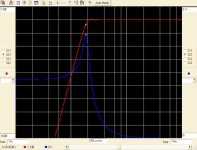
In the Derumbleizer you can see the peaking and the derived response is 6 dB/octave. It's lucky to have only 15 dB of crosstalk at 1 kHz.

Derived bass to mono Elliptic Equalization is very much like coping with derived crossovers.
The solution required to provide a symmetric second-order response was found in Mr. Self's "Design of Active Crossovers."
By putting an Allpass network in Mid to correct the phase response of the Side high pass filter a 12/db octave Vertical and Crosstalk slope can be obtained.
The result looks like this:
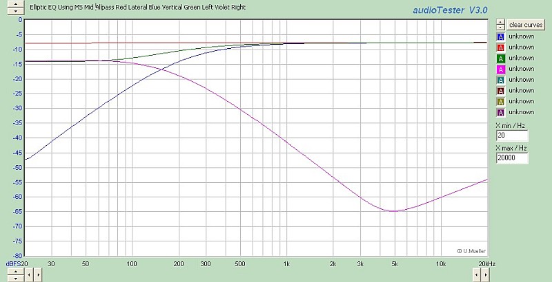
This particular filter is set for a 300 Hz vertical.
There is no peaking. The mono sum (red) is unity.
Both the vertical (blue) and crosstalk (violet) slopes are 12 dB/octave.
There is over 35 dB separation at 1 kHz.
More to follow...
As I mentioned earlier my interest in this thread came from experiments trying to improve on the simple first-order Elliptic Equalizers built into Neumann lathes. Filtering vertical in mastering to prevent overmodulation is the same process as filtering vertical warp on playback.
You can see that the Neumann EE-70 and EE-77 are quite simple.
Neumann EE70 "Elliptical" Filter Schematic
The later EE-77 ditched the inductor:
Neumann E77 Low Frequency Blend
The later VAB-84 used a different approach with a dynamic sliding filter and adds or subtracts Side to provide crossfeed.
Neumann VAB-84 Block Diagram Showing Dynamic Control of Side Information
All of the above are single-order: The Side "Vertical" filtration slope is 6 dB/octave and the Crosstalk slope is 6dB/octave.
The goal was to increase filter order for both crosstalk and vertical. The improvements are two-fold: There's less vertical and less crosstalk.
One can break a signal down into Mid Side and highpass filter Side to control vertical or one can lowpass filter Side and add/subtract it from Left and Right to do almost the same thing.
In either case one response is derived: It will have a 6 dB/octave slope regardless of the filter order and will peak around Fc.
An MS matrix with a 12 dB/octave highpass in Side will have a Vertical response that's 12 dB/octave but the crosstalk curve is 6 dB/octave. Left and Right will peak with hard-panned inputs.
An LR+/-S matrix with a 12 dB/octave low pass in Side will have a 12 dB/octave crosstalk slope but the vertical will be 6 dB/octave and peak near Fc.
With either approach the mono sum is constant.
In the Derumbleizer you can see the peaking and the derived response is 6 dB/octave. It's lucky to have only 15 dB of crosstalk at 1 kHz.
Derived bass to mono Elliptic Equalization is very much like coping with derived crossovers.
The solution required to provide a symmetric second-order response was found in Mr. Self's "Design of Active Crossovers."
By putting an Allpass network in Mid to correct the phase response of the Side high pass filter a 12/db octave Vertical and Crosstalk slope can be obtained.
The result looks like this:
This particular filter is set for a 300 Hz vertical.
There is no peaking. The mono sum (red) is unity.
Both the vertical (blue) and crosstalk (violet) slopes are 12 dB/octave.
There is over 35 dB separation at 1 kHz.
More to follow...
Last edited:
This seems to imply that you only need to worry if the current is big enough to flip the cartridge off the vinyl. I don't think that can be right.B l is exactly the same in both eqns and these are the two links between the Mechanical & Electrical worlds. You get B l directly from the sensitivity of the cartridge. If the force due to the current is much less than the tracking weight, it is of no consequence.
A bit more detail required here, I think. What was the level of THD/2nd harm?I tried to find a difference in THD and/or 2nd HD on test discs with IIRC, up to 100uA through the cartridges, but saw nothing.
I freely admit I have never tried this sort of experiment. But it seems to me extraordinarily unlikely that an MC cartridge that generates tiny signal currents could not have its linearity degraded by DC currents orders of magnitude higher. I am prepared to be convinced otherwise, but it's going to need some pretty solid evidence.
I haven't found a chart that goes below 40 AWG. What's the source for that?
That took awhile. I had difficulty as well: The CircuitCalculator.com Blog Wire Parameter Calculator
I was shocked that the pulldown went beyond 40GA. I think we can calculate the fusing current for 60GA. My 5-10X estimate is probably low for a straight wire.
Are you allowing for the fact that the wire is wound in a compact coil?
No. I'm sure that there would be lots of self-heating and that insulation breakdown would probably occur first.
I assume you mean a series resistor? That would play merry hell with the noise performance.
Well it would though my suggestion was for a MM cart not a MC. Again there are lots of MM designs that have a 1K-ish series Rin for RFI protection.
Someone worried about fault current might be willing to give up a few dB of noise figure to regain lost sleep. With a 1KΩ in series with a 600Ω DCR cart the 15V fault Pd drops from 375 to 120 mW. (I sleep fine without an Rin BTW.)
That calculator happily accepts 100 AWG. The resistance for a foot of such wire is 2 Megohm.That took awhile. I had difficulty as well: The CircuitCalculator.com Blog Wire Parameter Calculator
I was shocked that the pulldown went beyond 40GA. I think we can calculate the fusing current for 60GA. My 5-10X estimate is probably low for a straight wire.
Guaranteed, I fear. My experience with transformers etc is that the insulation always fails first.No. I'm sure that there would be lots of self-heating and that insulation breakdown would probably occur first.
I was thinking of MM. 1k is obviously crazy for MC.Well it would though my suggestion was for a MM cart not a MC. Again there are lots of MM designs that have a 1K-ish series Rin for RFI protection.
This seems to me to be heading off in quite the wrong direction. With a blocking cap you lose nothing.Someone worried about fault current might be willing to give up a few dB of noise figure to regain lost sleep. With a 1KΩ in series with a 600Ω DCR cart the 15V fault Pd drops from 375 to 120 mW. (I sleep fine without an Rin BTW.)
- Status
- Not open for further replies.
- Home
- Source & Line
- Analogue Source
- What is the ideal conventional rumble filter?- Douglas Self