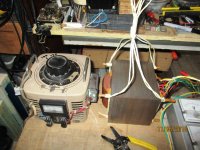
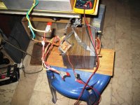
Mains wires (thicker black wires on upper side of fotograph): Probably correct, because the other wires gave reasonable voltages. But please check the resistances of all wire combinations. The mains wires should have the highest resistance (for a down-stepping transformer!).
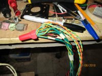
I am not sure about the (thinner) black wire. It looks to me as a midway of the orange windings because of equal voltages on both orange wires. What I dont understand yet are the voltages black-blue 1/2.
Could you check with an Ohm-meter, which windings are separate (e.g., make the orange wires one winding without connection to the blue wires?) A diagramm with the ohmic resistances between all wires should give then a clear picture of your transformer.
Last edited:
Could you check with an Ohm-meter, which windings are separate (e.g., make the orange wires one winding without connection to the blue wires?)
Thanks for the reply, do you mean connect the 2 orange wires together and take an resistance reading and then do the same to the blue wires?
Not exactly. I would make a list like this:
orange 1 - orange 2 : xxx Ohm
orange 1 - black (thin) : xxx Ohm
orange 1 - black (thick, mains?): xxx Ohm
orange 2 - black (thin): xxx Ohm
orange 1 - blue 1: xxx Ohm
blue 1 - blue 2: xxx Ohm
blue 1 - black (thin): xxx Ohm
and so on. So all combinations should be measured.
Then you can identify, which windings are separate and whether the thin black is in the middle of just the orange winding(s).
A further hint might be the thickness of the wires: Are the orange/blue/black wires of the same wire gauge?
Thanks, I will hook up the powermake a list and post on Monday, as family duties prevail today.
Note sure if I fully understand this quote:
Is an isolation transformer the same as a AC Variac (I have one), not sure if I fully understand the part about the isolation transformer and the live wire bit.
Cheers
Note sure if I fully understand this quote:
A safety note is due here: I use an isolating transformer for doing such measurements. It may not only prolong my life substantially, it avoids killing test equipment by inadvertenly connecting a life wire to the ground terminal of the multimeters. So check your secondary windings with a Ohm meter for a possible connection to the primary winding (auto transformers have this!).
Is an isolation transformer the same as a AC Variac (I have one), not sure if I fully understand the part about the isolation transformer and the live wire bit.
Cheers
I hope I am not wrong, but a Variac alone will NOT provide galvanic isolation. You can check this by measuring the resistance between the wires of the inlet plug and the wires of the variac output. If there is any measurable resistance between an ingoing and an outgoing wire, there is a direct conductive connection between mains and output. When you use your phase tester on the variac output plug, you will very likely get a signal on one of the wires.
An isolation transformer has a primary winding and a secondary winding (with an equal number of wire turns as the primary winding to make the output voltage equal to the input voltage). Thus there is no conductive linkage between mains input and output.
Regarding the life wire: I dont know what wiring scheme is used in Kanada, in Germany the Neutral wire is connected at the power line entrance into the house with a safety earth (called ground or earth). This earth connection runs as a separate wire (green-yellow in Germany) as a protective earth. The Life wire is on the 230 volt potential relative to the neutral wire. When you touch the life wire, you get the full voltage difference, because you are on "earth potential". This indicates already the potential problem with your measuring instruments: When one pole of the instrument is connected to the protective earth and you plug into this position the wire, which is on the life potential, you create a massive short. Digital multimeters may have fully isolated input plugs (as the Agilent 34465A), but oscilloscopes, e.g., usually do not provide earth-free inputs. So again my advice of acting really carefully. Improper handling of mains voltages can ruin a lot.
The wires after an isolation transformer do not have the earth reference anymore, so you can touch the wires without harm (but not both simultaneously, the voltage difference is still present, of course!).
A probably much better explanation can be found here: https://en.wikipedia.org/wiki/Isolation_transformer
Last edited:

What is the best way to measure transformer output?
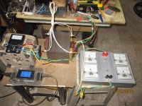
if it is a mains transformer, usually - at least here in Europe for small industrial transformers - we admit a 4% voltage drop between unloaed and normally loaded :- power it on the correct main voltage (with a monitored Variac if possible).
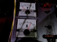
- measure the output voltage unloaded.
- load the transformer until the voltage drops to 4% and measure simultaneously the matching current in the load.
You have then the nominal design output voltage and current.
Note : if there's several windings on the transformer, all should be loaded at the same time to make correct a measurement, since all the power of the transformer is to be distributed to each loaded winding. That means that if you load only one winding, you may find superior performance than the nominal design, that would not occur if the transformer was suitably loaded on all of its winding.
T
temperature rise is also a factor, you can load lour transformers according to how long it is going to be energized, for example, microwave oven transformers are run with high flux and so will rum very hot for more than 1 hour of use...
transformer volt ampere capacities are initially based on core area with a set of frequency and flux density, in my experience, not all of the core va capacity is put to good use, the winding windows limits the size of wire you can stick in, and the temperature rise that comes with loading is another...
another good source of information would be the ARRL handbooks, i happen to have the 1960 edition, but other editions can be found in the net...
no, an isolation transformer has a primary winding and secondary windings that are completely separate from each other, the variac otoh is like an auto transformer with wiper arm to select taps on a continuous basis...Is an isolation transformer the same as a AC Variac (I have one), not sure if I fully understand the part about the isolation transformer and the live wire bit.
Last edited:
there are two tests you can do with your transformer, first is the no load or core test, second is the short circuit testing wherein all secondary windings are shorted out and a variac at the primary is used to adjust input voltage that allows the primary rated current to flow....these are non destructive tests....https://eepower.com/technical-articles/open-circuit-and-short-circuit-tests-in-transformers/#
Attachments
-
 296_o.jpg482.4 KB · Views: 64
 -
 312_o.jpg394.2 KB · Views: 67
 -
 384_o.jpg413.7 KB · Views: 72
 -
 688_o.jpg488.6 KB · Views: 73
 -
 872_o.jpg470.8 KB · Views: 65
 -
 14681731_1248029041885394_524840871389441540_n.jpg103.3 KB · Views: 63
 -
 14681764_1248029161885382_6804992629624912745_n (1).jpg71.7 KB · Views: 66
Thanks a lot for all the help. A lot to digest at the moment. Will do some reading and testing and try to come up with some useful values. Will let you know progress.
Cheers
Cheers
I own the 2021 edition, which devotes only one and half page to power transformers. Figure 7.4 on page 7.3 shows a nice scetch on how to use an isolation transformer, where it's secondary goes into the DUT (device under test) via a light bulb. The latter indicates higher currents.another good source of information would be the ARRL handbooks, i happen to have the 1960 edition, but other editions can be found in the net...
All in all, the RDH chapter is much more informative (albeit from the pre SI era).
- power it on the correct main voltage (with a monitored Variac if possible).
- measure the output voltage unloaded.
- load the transformer until the voltage drops to 4% and measure simultaneously the matching current in the load.
Where does one measure the output voltage unloaded?. Do you mean measure across each set of similar wires and add the voltages to obtain one total value. Really new to this hobby😉
What about the promised list of resistance measurements across all combinations😉
I dont want to urge you to anything, but in case you want to use this transformer for something (e.g.,for a +/- 25 Volt DC power supply), you need to know the details of all windings. For example, is the secondary winding a single one with taps in between? Or are there separate windings for different voltages, maybe center-tapped? With the completely risk-free resistance measurements we can work this out.
Btw, do you know these tutorials:
https://www.electronics-tutorials.ws/inductor/inductor.html
https://www.electronics-tutorials.ws/transformer/transformer-basics.html
I am working on it, need some time, many projects in the que. Many questions to be answered . Many duties around the property. 🙂👍
Where does one measure the output voltage unloaded?. Do you mean measure across each set of similar wires and add the voltages to obtain one total value. Really new to this hobby😉
Aw, sorry - I figured that you had identified the windings ends... If not, it becomes complicated ! Try to identify the primary - usually it's the one that has the highest DCR, if the transformer is a stepdown one, but this is not an evidence, though !
T
Hello guys,
Thanks for all the input and info you have helped with. I hooked up the power with variac and both with and without a dim bulb tester and I tested the orange-orange wires. At 110V on the variac, the orange wires tested 52V. I switched to ohms reading and the reading started high and then settled around 30 ohms for a second, and then fell to zero.
Not knowing enough and having weird things happen is not the way I would like to learn, and playing with electricity I find to be a bit unnerving
So this is just one transformer that I gutted from an old receiver, so it may be defective. I think that I will read up on transformer principles and may even buy the ARRL 2023 book to have around, but for now, my testing on this transformer is finished. I thank you all for the help. I may come back to it at a later date.
i have the 1960 ARRL handbook, it is also a nice source of practical information and construction practices...
- Home
- Amplifiers
- Power Supplies
- What is the best way to measure transformer output?