Transformers, despite being the heart of every one of these treasured electronic things, are still something of a black art to me. In discussions here about renovating my old components, I've been told to build new power supplies in outboard chassises to reap the benefits of lowered noise, most notably in the Big Sky Adcom thread. I'm ok with the idea, but what if I don't have the value of the original transformer and I decide I want a nice shiny new one without any de-lamination? How do I measure the output of the original transformer to find out the needed value for the new one? Is it just as simple as knowing the output voltage(s) and applying a formula?
Check the resistance, more turns have higher resistance.
Buy a good meter, most are cheap, and not accurate in the x1 ohms range.
Then feed mains voltage on high voltage side, and see the output in open condition.
Then use a filament lamp as dummy load, measure again.
Then use in circuit.
Buy a good meter, most are cheap, and not accurate in the x1 ohms range.
Then feed mains voltage on high voltage side, and see the output in open condition.
Then use a filament lamp as dummy load, measure again.
Then use in circuit.
Before deciding on a transformer, you should know the amplifier circuit and the speaker load it's driving. F.ex. when I sorted my Acurus amp, somebody pointed out that since my speaker was a 4 Ohm speaker, that the amp would be happier with a lower voltage trasformer than the stock 93VCT and I found an 80VCT. Today I might aim even lower voltage, so I could use 50V caps instead of 63V...
i am not a fan of outboard power supply, outboard power transformers maybe...Transformers, despite being the heart of every one of these treasured electronic things, are still something of a black art to me. In discussions here about renovating my old components, I've been told to build new power supplies in outboard chassises to reap the benefits of lowered noise, most notably in the Big Sky Adcom thread. I'm ok with the idea, but what if I don't have the value of the original transformer and I decide I want a nice shiny new one without any de-lamination? How do I measure the output of the original transformer to find out the needed value for the new one? Is it just as simple as knowing the output voltage(s) and applying a formula?
get yourself a copy of RDH4 chapter 5..... http://ds.agavaceae.ru/books/RDH/CHAPTR05.PDF

How do I measure the output of the original transformer to find out the needed value for the new one? Is it just as simple as knowing the output voltage(s) and applying a formula?
You'd want to match the unloaded output voltage (measure with a DVM on AC volts range) but you'd also need the same (or better) regulation. The latter parameter is a measure of how much loss of output voltage you incur on load. Can't be measured directly but a good proxy for this is simply weight. The heavier, the better the regulation.
transformers are all about the mass of irons contained therein..
surely you are not going to get a lighter weight than what is before...
volt amperes, VA is the measure of capacity, know all your secondary volt ampere requirements and get one that is better...
surely you are not going to get a lighter weight than what is before...
volt amperes, VA is the measure of capacity, know all your secondary volt ampere requirements and get one that is better...
If you match the weight the regulation will usually be fine.you'd also need the same (or better) regulation.
If you over-size, then like the hotrodder dropping a Hellcat engine into a Mini-- you better know what you are doing.
What about replacing the transformer* for a type with same or slightly higher current ratings? If you buy an R-core type you almost can not go wrong. These don't need to be used externally as the stray field is extremely small. Two birds with 1 stone!
*Of course not mentioning what the brand and type of the amplifier is like advertising "red car for sale" and then wonder why you get so many strange reactions. For exact answers techs need exact information to solve your issue.
So just check the service manual and/or ask owners of the very same device what the voltages are. Check the specified output power of the amplifier and make an educated guesstimation of the needed VA rating. Many here will know the device and possibly the exact voltages and currents too. The negative may be that a transformer is used with more than just the 2 windings for the power amplifier like extra 2 x 15V for opamps, 1 x 7V for digital stuff etc. In that case practically only the original one is usable.
Last edited:
Just post a picture, if you have the transformer with you.
I did say measure on load and use if suitable, in Post# 2 above.
I did say measure on load and use if suitable, in Post# 2 above.
i have been doing transformers since 14, now ia am 70....i had a fair share of failures too...but that is how i learn..
today folks are lucky for forums like this to get education and learn from....
prior to the advent of world wide web, no such facility except for schools and inversitties...
prior to the advent of world wide web, no such facility except for schools and inversitties...
Well I appreciate the answers but this has sort of gone off the path. I probably shouldn't have said a thing about the preamp or outboard transformers because that really muddied the waters. So let me try this a different way.
If I go to the Plitron catalog (now its Noratel), I see exactly three electrical values provided: power (VA) and secondary voltage/current (number of taps and the volts and amps for each). There's no mention of anything else, other than physical characteristics. To the production people at an electronics manufacturer nothing else matters. The engineer designed the circuit and sent the schematic to them and it says something like "TFMR, 115VAC mains, 2x45VAC@2A secondary, 160VA". They're going to look at the Plitron or Hammond catalogs and see a long list of transformers and only those electrical values. They get to decide the size and weight and possibly the type, because they get to figure out how to fit everything in a box. (I know the amp is going to go through revisions as they work out the package and things like RF, so I'm simplifying here.)
So, pretend you have a transformer in a project and it broke. Like many transformers out there it has a small decal on it that gives you that VA number. You have a big box of new transformers sitting in storage for a decade and when you open it you find that all their little decals have fallen off from humidity or vibrations or verruca elves or whatever. All of them close in size to the one in your project and they all have the same number of taps, but you're not going to know which one has the right VA unless you test each one.
Cliff's notes: I want to know how to test a transformer with unknown specs to find out the VA.
I hope I've brought a better focus to my question.
Without pictures, focus is difficult.
No need to be coy, post a picture of the old transformer, and what you have in storage.
And the unit you claim needs a replacement transformer.
No need to be coy, post a picture of the old transformer, and what you have in storage.
And the unit you claim needs a replacement transformer.
You simply don't get what I'm asking, Naresh. I'm not being coy. I tried to explain things in a conversational manner, and that turned out to be a waste of everyone's time. So from now on I'll skip anecdotes and humor and just lay out the facts.
Forget my earlier posts. I want to know how to do the following:
Pull the power transformer out of any stereo component. Measure that transformer so that I can compare it to the single-line description of any audio power transformer in a catalog.
For example, the Hammond 260 series has 8 models, and the ONLY values shown are AC high voltage secondary tap values, VA, and dimensions:
https://www.partsconnexion.com/media/pdfs/Hammond260SeriesSpecSheet.pdf
You don't need pics for that.
In a transformer the primary produces a varying resultant flux that is dependent on the supply voltage. More current in the secondary causes it to produce more opposing flux which is counteracted by the primary producing more flux as a response. This means, when the current in the secondary increases or decreases the current in the primary must at all times produce a resultant flux that is dependent only on the primary voltage. In short, magnetically, the magnetic fields of the primary and secondary act in opposition with the primary producing more magnetic flux that is governed by the primary.
A transformer must obey the rule:
Which is another way to say, the current in the primary must follow the current in the secondary. This is an approximation which is true provided the magnetising current is insignificant compared with the rated primary current.
A transformer must obey the rule:
Code:
d/dt {Np.(Φp - Φs)} = V.sin(ω.t)Which is another way to say, the current in the primary must follow the current in the secondary. This is an approximation which is true provided the magnetising current is insignificant compared with the rated primary current.
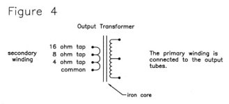
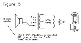
Now I'm relieved that between Tony's book and edbarx' knowledge, there is sufficient information and brainpower to rebuild civilization from scratch after the Armageddon. I would like my attached illustrations included in that pamphlet.
But until then here's my practical take on transformers: Totally opposite to three-legged fuses aka transistors, transformers are four-legged (at best) short circuits (worse actually) impervious to damage! But both transistors and transformers can be analyzed in terms of wimpy side and hefty side. Wimpy, hefty. Start with that. Any questions?
But until then here's my practical take on transformers: Totally opposite to three-legged fuses aka transistors, transformers are four-legged (at best) short circuits (worse actually) impervious to damage! But both transistors and transformers can be analyzed in terms of wimpy side and hefty side. Wimpy, hefty. Start with that. Any questions?
Attachments

You may want to learn the "iron test" and the "copper test", the "transformer equation" and read a book on transformers (hint: tough information as these are complex). To keep it simple one could just look at primary and secondary voltage(s) and VA ratings and add a margin to that just to be sure. Knowing the load in various circumstances is also a must. A too light transformer will create issues whereas an overrated transformer won't harm anything except that it wil be large and heavy. The word "audio" is of not much importance, it is about other properties mainly. If you don't have an electrical background and/or lack the basic knowledge of electrical items you maybe want too much as transformers are of the more complex devices with many details and calculations.Forget my earlier posts. I want to know how to do the following:
Pull the power transformer out of any stereo component. Measure that transformer so that I can compare it to the single-line description of any audio power transformer in a catalog.
For example, the Hammond 260 series has 8 models, and the ONLY values shown are AC high voltage secondary tap values, VA, and dimensions:
https://www.partsconnexion.com/media/pdfs/Hammond260SeriesSpecSheet.pdf
You don't need pics for that.
Of course people here ask for pictures, that's is because many of them are techs. To be able to check if that transformer really needs replacement and/or to offer alternative repair methods. People thinking in emotions often want something that makes little sense and only will cost money, effort and will bring no real gains. A trained tech may want to prevent the layman from that.
Last edited:
- Home
- Amplifiers
- Power Supplies
- What is the best way to measure transformer output?