Hi guru
Hi guru,
Thanks for the comments.
IGBT's from APT doesnot have second breakdown voltage.
Thats why we have choosen them and thats there biggest advantage over BJT's.
We have further increased the power output to 1900WRMS@2 ohms with rails at 95V and using 3 pairs of IGBT's which increases the safety margin at reactive loads.
The harmonics does effect the sonic quality only when PSRR is low.
regards,
Kanwar
amplifierguru said:Lars,
Aren't you being a little unfair to Kanwar's IGBTs suggesting a 200W rating due to 2vx100A on the saturation limit. You could equally well have used 4vx200A = 800W on the same curve. This is not definitive for the device dissipation.
Better to consider what it can do practically in an amplifier i.e. at the supply rail voltage of 80V Kanwar is using. Since they are essentially a BJT for power they should presumably be derated from the 390W case dissipation at 25C to 278W at 75C. This gives current of 3.5A at zero crossing for reactive (real) load driving ability. As with most rugged BJTs this can be relaxed due to pulse duration and duty cycle. In Kanwars application we can assume seconds+ and 50%, which could reasonably reliably double the current output ability given the ruggedness.
So I would put it at around 550W giving 7A at 80V rails. But where is that BJT second breakdown?
Can you imagine the hash on the supplies at such current /power levels. Attached is a pic of the supply of my 250W /8ohm amps supply rail on the circuit board when output is 5W rms into 8 ohms. See the induced harmonics due to the Class AB half currents. This is what lurks on every AB supply waiting for a poor PSRR stage referencing to the supplies.
Hi guru,
Thanks for the comments.
IGBT's from APT doesnot have second breakdown voltage.
Thats why we have choosen them and thats there biggest advantage over BJT's.
We have further increased the power output to 1900WRMS@2 ohms with rails at 95V and using 3 pairs of IGBT's which increases the safety margin at reactive loads.
The harmonics does effect the sonic quality only when PSRR is low.
regards,
Kanwar
Amplifierguru: Sorry i did'nt mean to be hard on Kanwar's IGBT's. Just reading the datasheet. If you look at fig 9, you will see it can not carry 200 A with 4 V drop to give 800 W like you suggest. It will be a violation of the maximum specs. This device can only carry maximum 100 A. And t = 100 deg C. (Which is actually a lot of current).
My opinion is still that IGBT's are not a reliable option at least for my area, which is wideband hifi amplifiers. But i guess OK for PA amplifiers with limited bandwidth. 🙂
My opinion is still that IGBT's are not a reliable option at least for my area, which is wideband hifi amplifiers. But i guess OK for PA amplifiers with limited bandwidth. 🙂
Hi
Dear LARS,
Professionals always love to have hardships and challenges to face, nothing to worry get as hard as you can.😉
Your area covers only domestic + audiophile and home audio + DIY also .
Our area is pro-world for pro audio .
These IGBT's are not worth in AUDIOPHILE amps.
But Mosfets definately worth in audiophile gear.
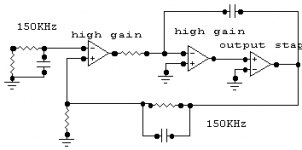
Since you are talking about widebandwidth , our 2400W Stallion has power bandwidth of 200KHZ, is'nt it HI-FI.😀 😉
regards,
Kanwar
Lars Clausen said:Amplifierguru: Sorry i did'nt mean to be hard on Kanwar's IGBT's. Just reading the datasheet. If you look at fig 9, you will see it can not carry 200 A with 4 V drop to give 800 W like you suggest. It will be a violation of the maximum specs. This device can only carry maximum 100 A. And t = 100 deg C. (Which is actually a lot of current).
My opinion is still that IGBT's are not a reliable option at least for my area, which is wideband hifi amplifiers. But i guess OK for PA amplifiers with limited bandwidth. 🙂
Dear LARS,
Professionals always love to have hardships and challenges to face, nothing to worry get as hard as you can.😉
Your area covers only domestic + audiophile and home audio + DIY also .
Our area is pro-world for pro audio .
These IGBT's are not worth in AUDIOPHILE amps.
But Mosfets definately worth in audiophile gear.
Since you are talking about widebandwidth , our 2400W Stallion has power bandwidth of 200KHZ, is'nt it HI-FI.😀 😉
regards,
Kanwar
Hi Kanwar,
I cut my teeth designing Pro-Audio amplifiers so know the issues well. They must be bulletproof - but musos know a clean top when they hear it, even with noise overlaod impacted eardrums.
Ritchie,
I've not worked with IGBTs and I'm not sure where the second breakdown went - and the repercussions for all BJTs?
Hi guru
Hi guru ,
I am already aware of the fact that you were also a professional and thats your biggest advantage as guru.😉
The pro-amps must be bulletproof, yes its true to the nature.
One more thing , have you ever taken the feedback after the output inductor.[it is taken before the inductor in typical designs]
We have also noticed one thing that inverting input results more damping factor than non-inverting input with many designs including BJT's and Mosfets.
Hi Ritchie,
We have contacted APT about the issue of Second Breakdown Voltage in IGBT's.
They have told us that , they were using an Advanced Metal Gate Planar Cell Fabrication Process, which eliminates the second breakdown voltage effect in IGBT's and this is unique and only used by them because they have developed it using their own patented technology.
For our further satisfaction , we have driven the IGBT upto its limits in linear range and their was no sign of breakdown occurs.
regards,
Kanwar
amplifierguru said:Hi Kanwar,
I cut my teeth designing Pro-Audio amplifiers so know the issues well. They must be bulletproof - but musos know a clean top when they hear it, even with noise overlaod impacted eardrums.
Ritchie,
I've not worked with IGBTs and I'm not sure where the second breakdown went - and the repercussions for all BJTs?
Hi guru ,
I am already aware of the fact that you were also a professional and thats your biggest advantage as guru.😉
The pro-amps must be bulletproof, yes its true to the nature.
One more thing , have you ever taken the feedback after the output inductor.[it is taken before the inductor in typical designs]
We have also noticed one thing that inverting input results more damping factor than non-inverting input with many designs including BJT's and Mosfets.
Hi Ritchie,
We have contacted APT about the issue of Second Breakdown Voltage in IGBT's.
They have told us that , they were using an Advanced Metal Gate Planar Cell Fabrication Process, which eliminates the second breakdown voltage effect in IGBT's and this is unique and only used by them because they have developed it using their own patented technology.
For our further satisfaction , we have driven the IGBT upto its limits in linear range and their was no sign of breakdown occurs.
regards,
Kanwar
Hi Kanwar,
Most of my power amplifier designs use nested feedback loops to virtually eliminate output stage distortions (particularly those that surface under reactive loads). Adding a load dependant extra pole (by way of taking feedback from after the output L) could seriously compromise the stability of multiple loops. By the way my output inductors are never more than 15 turns of enamelled wire in 2 layers on a 1 watt c.f. resistor. My amplifiers are generally more stable than many single loop designs as I employ pole-zero cancellation to bring phase shift back to around 90 deg at closure.
Most of my power amplifier designs use nested feedback loops to virtually eliminate output stage distortions (particularly those that surface under reactive loads). Adding a load dependant extra pole (by way of taking feedback from after the output L) could seriously compromise the stability of multiple loops. By the way my output inductors are never more than 15 turns of enamelled wire in 2 layers on a 1 watt c.f. resistor. My amplifiers are generally more stable than many single loop designs as I employ pole-zero cancellation to bring phase shift back to around 90 deg at closure.
amplifierguru said:.............my output inductors are never more than 15 turns of enamelled wire
Good...
amplifierguru said:.............in 2 layers on a 1 watt c.f. resistor.
Bad....one layer better....and NOT on resistor...
Why so baaaad Mikeks?
Not wound by peruvian virgins ....
Oh and R=1 ohm so there's no ringing or response errors with differing loads and the RC to ground is upstream so it doesn't interfere and is always 10ohm/100nf so not to load output stage at uhf.
Not wound by peruvian virgins ....
Oh and R=1 ohm so there's no ringing or response errors with differing loads and the RC to ground is upstream so it doesn't interfere and is always 10ohm/100nf so not to load output stage at uhf.
Most of my power amplifier designs use nested feedback loops to virtually eliminate output stage distortions (particularly those that surface under reactive loads). Adding a load dependant extra pole (by way of taking feedback from after the output L) could seriously compromise the stability of multiple loops. By the way my output inductors are never more than 15 turns of enamelled wire in 2 layers on a 1 watt c.f. resistor. My amplifiers are generally more stable than many single loop designs as I employ pole-zero cancellation to bring phase shift back to around 90 deg at closure.
So you are Cherry follower... and how many loops do you usually put in the nest?
Mike prefers wounded by Halcro ...Not wound by peruvian virgins ....
nested feedback / inductor
Hi amplifier guru,
tell us more on nested feedback. You never contributed to my thread some months ago looking for just this type of info.
Mikeks, why use one layer on a long inductor?
For minimum resistance I use a multilayer coil wound on a temporary (air) core with a diam about 2.5*width of coil gives maximum inductance for a set length of wire. i.e. minimum resistance /uH. the coil winding proportions should be approx square i.e.4 layer & 4 turns/layer alternatively omit 1 turn off top or bottom layer to give 14 or 15 turns in total.
1 layer Inductor
I would guess it has to do with these properties of the single layer inductor:
1..Lower Q, and so less ringing.
2..Lower transfer capacitance, maybe not very important in this application.
Another thing is, why have the inductor at all? After all it's basicly a band aid solution to an unstable design. So the inductor protects the output stage against load capacitance, that would send the amplifier to self oscillation mode.
I have been living off amplifier construction for 15 years, and i have never used an inductor in the output stage of any of my amplifiers. Except class D of course 😀
If you follow some simple rules, you can make also your amplifiers stable against capacitive load, without the inductor.
🙂
Alexander Power Amplifier (PDF)
Alexander Power Amplifier (Current Feedback design).
This war a nice Amplifier I play about 10 year with this design.
Monoblock
112.000 uf
1000Va, toroid 2x 42v
Alexander Power Amplifier (PDF File)
http://members.home.nl/wincent24/AN211.pdf
Greetings,
Rudy
Alexander Power Amplifier (Current Feedback design).
This war a nice Amplifier I play about 10 year with this design.
Monoblock
112.000 uf
1000Va, toroid 2x 42v
Alexander Power Amplifier (PDF File)
http://members.home.nl/wincent24/AN211.pdf
Greetings,
Rudy
Hi,
the other purpose of the output inductor is to block RadioFrequency and other interference (picked up by the speaker lead/aerial) entering the feedback loop straight to the -ve base of the LTP. The lower leg of the 2 pole filter is the capacitor half of the Zobel network.
the other purpose of the output inductor is to block RadioFrequency and other interference (picked up by the speaker lead/aerial) entering the feedback loop straight to the -ve base of the LTP. The lower leg of the 2 pole filter is the capacitor half of the Zobel network.
Hi dimitri,
I use nested loops , usually only two and quite different from Cherry - mine are quite different!
Hi Lars,
Many amplifiers show an instability under small cap loading , then none for medium loading, then ringing on high cap loading. One solution is to slug the amp with Ccomp but performance is lost. A small value output inductor protects the amp from small cap instability, and RF pickup as mentioned By Andrew T, which can easily feedback through my feedback capacitor (integrating main loop). Large cap loading impacts the loop in a different region where stability can be ensured with feedback poles (loop zeros).
Lastly Andrew T,
Sorry I was not a member of this forum then, or I would likely have contributed.
I use nested loops, usually only two and quite different from Cherry - mine are quite different!
Sorry I was not a member of this forum then, or I would likely have contributed.
It is never late to make a contribution, guru 🙂
OK, I played with nested loops in the past and prototyped all Cheery circuits. While the idea is appealing, it required special forward path for the implementation. I’ll explain:
1)inverting output stage with gain. Not that simple as emitter follower, slow discharge of output devices – common mode current spikes.
2)single output from the input stage – use of current mirror, again extra complexity, all this additional devices in forward path represent their own minor poles/phase lag.
For the conventional forward path: single-ended input stage, voltage amplifier stage and output follower there exist only one loop – from the output to the input of the VAS. But this loop is less stable than conventional Miller compensation. If you would like to utilize differential output from the input stage there is no possibility to arrange nest at all.
So, once you start to spread wisdom here 🙂, what was your solution?
You can whisper it right now when Mike and Lars are dreaming in bed 😀
- Status
- Not open for further replies.
- Home
- Amplifiers
- Solid State
- What every Class AB builder needs to be constantly aware of