Yes, and 0.15 above around 1k, and 0.1 above a few k.I was literally noticing a 0.2dB change in the amount of baffle step correction in the midrange
Agreed 100% (except possibly only for where you express your dislike for asymmetrical slopes: these can work very well in my experience).
Just for grins, here's the result of one of my own passive crossover labours 🙂
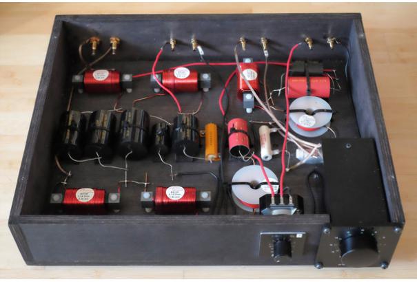
Marco
I got an ulcer just from looking at that.
A carefully crafted active crossover will beat a carefully crafted passive crossover every single time. (Except for hiss.)
What I am not so sure about is the way everyone uses miniDSP casually - just dial in a frequency, LR48, or FIR, and fire up.
Unless the planets align and the acoustic phase are the same for both drivers, you will need biquad programming to get the phase relationships between the drivers right. It is true that I tried to argue in the Butterworth vs LR thread that phase coherence is not a requirement - but a random phase relationship can only result in a frequency response dip, which must be audible.
Hence, all the advantage a stock DSP setting has, is a steeper slope.
If you take time to craft a passive it will do a lot more for you. (Of course the same is true if you take time to craft an active.)
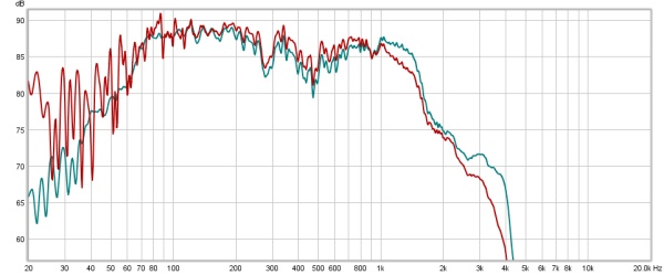
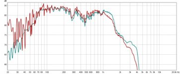
With just an electrical second-order, I am not too far away from an active LR4. The green line is the passive. Note the obvious insertion loss. As you can see the knee of the passive is very sharp indicative of a moderately aggressive Chebyshev alignment. That, coupled with the inherent inductance of the woofer itself, are not that far behind active LR4 in suppressing the cone break-up at 3-4k.
That's why I claimed, passive may not win over LR 24dB/oct, but it will be a good fight, not a round one knock-out.
(These are half-space measurements. Below 100Hz is just background noise. Please ignore that.)
What I am not so sure about is the way everyone uses miniDSP casually - just dial in a frequency, LR48, or FIR, and fire up.
Unless the planets align and the acoustic phase are the same for both drivers, you will need biquad programming to get the phase relationships between the drivers right. It is true that I tried to argue in the Butterworth vs LR thread that phase coherence is not a requirement - but a random phase relationship can only result in a frequency response dip, which must be audible.
Hence, all the advantage a stock DSP setting has, is a steeper slope.
If you take time to craft a passive it will do a lot more for you. (Of course the same is true if you take time to craft an active.)
With just an electrical second-order, I am not too far away from an active LR4. The green line is the passive. Note the obvious insertion loss. As you can see the knee of the passive is very sharp indicative of a moderately aggressive Chebyshev alignment. That, coupled with the inherent inductance of the woofer itself, are not that far behind active LR4 in suppressing the cone break-up at 3-4k.
That's why I claimed, passive may not win over LR 24dB/oct, but it will be a good fight, not a round one knock-out.
(These are half-space measurements. Below 100Hz is just background noise. Please ignore that.)
Attachments
Indeed.Yes, and 0.15 above around 1k, and 0.1 above a few k.
For a 3Khz crossover, I can "notice" less than a 0.2dB change in relative attenuation between the two drivers, provided that the balance is very close to correct to begin with and the driver responses are pretty flat. (obviously if you are 2dB away to start with or the drivers are very non flat +/- 0.2dB makes little difference as you're so far away from neutral)
I said 0.2dB earlier because I find that a shelf change at a 3Khz crossover quite obvious - I can sit down and put a familiar recording on and within seconds I'll know whether it is boosted or cut by 0.2dB or not. It changes the apparent imaging quite a lot.
0.1dB I do find noticeable but I'm not as confident about detecting it, and I'm not sure whether I would detect it reliably with blind testing or not.
A 0.1dB change I found would sometimes take me a few days of listening to identify it and decide it didn't sound quite right so its right on the threshold of perception for me. With it out by that much something didn't quite seem right but it was hard to identify what the problem was, it just sounded wrong.
Towards the end of fine tuning the crossover I was making these very small 0.1 dB changes to the midrange and tweeter levels either side of my initially calculated design, listening for a few days then reverting the changes again.
Funny thing is despite testing +/- 0.1 and 0.2dB either side of the original design for both midrange and tweeter levels, I found I kept coming back to the initial design calculated using vituixcad and preferring it. It seems I got the baffle step attenuation and tweeter attenuation levels spot on in the simulation - whether by design or luck I'm not sure when my nearfield splicing of the woofer measurement was less than perfect. 🙂 I couldn't improve on it with empirical adjustments.
In fact out of the entire design that I did in virtuixcad, over a few months of listening I only made two changes that stuck - I increased the baffle step coil value quite a bit to push the rollover frequency down a bit, (with the effect of dropping an octave of the low midrange centred around 300Hz by about 0.5dB) and I increased the first high pass filter cap on the tweeter by 0.2uF which raised the response in the presence region around 3Khz by about 0.4dB over about an octave.
Both changes don't sound like much but they completely changed the imaging and presentation of the speakers for the better, from slightly wooly and laid back/recessed sounding to somewhat more forward and revealing, but still clean and easy to listen to with no harshness.
Those are the kind of small changes that are sometimes needed to go from OK to sounding great, and it takes time and patience and experience to know exactly what to change if its not quite sounding right.
Last edited:
Simon, the image you posted (of your recent crossover) is not working. Can you provide a working link? I was interested to see what you did with the all pass on the tweeter, as I'm trying to redo my crossover at the moment with a lower cross point, and I've got a stubborn 40 deg difference that I'm trying to get rid of 🙂 The phase is tracking well it is just 40 degrees out 😕
Tony.
Tony.
What I meant is that you can certainly use vinyl with active...
Actually, DSP provides absolutely astonishing immensely wonderful help for vinyl record playing: processing to remove ticks-and-pops and vinyl noise. No doubt there are other corrections possible apropos stylus errors, arm geometry, resonances, low freq grooves, inner groove error, and much more.
Long ago, when I transferred my large vinyl collection to dots-and-dashes, I couldn't be more joyed at the improvement in the sound of my well-loved recordings.... and still do.
Can that processing be done in real-time?
Astonishing. Wonderful.
B.
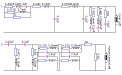
Hmm, the attachment seems to have vanished from the post, and I have no way to edit the message after the 30 minute edit window. I'll try attaching it again here. BTW Vituixcad always shows inductors as an inductor in series with a resistor - all the "resistors" in series with inductors that are below 1 ohm simply represent the DC resistance of the inductor. Just in case anyone thought I was going mad sprinkling extra resistors everywhere... 🙂Simon, the image you posted (of your recent crossover) is not working. Can you provide a working link? I was interested to see what you did with the all pass on the tweeter, as I'm trying to redo my crossover at the moment with a lower cross point, and I've got a stubborn 40 deg difference that I'm trying to get rid of 🙂 The phase is tracking well it is just 40 degrees out 😕
It's actually two cascaded first order all pass filters to get sufficient delay for what I needed.
Vituixcad provides all pass filters (only 1st order unfortunately) as a block you can add based on the roll over frequency and load impedance, so they're very easy to add and adjust. Maybe enter your existing crossover and driver measurements (including at minimum impedance and on axis frequency response, it can also take additional polar measurements) into Vituixcad and give it a try ?
It's the first time I've tried to use a passive all-pass filter in a crossover and it seemed to do the trick nicely, with pretty good phase tracking between 2 and 5Khz. (3Khz crossover frequency)
Getting good tracking at 6Khz is not easy because the full range driver itself is non-minimum phase at high frequencies due to the whizzer cone, with an excess group delay bump around 6Khz where the two cones cross over. This complicates things a bit and is one reason I brought the original 4Khz crossover down to 3Khz...
Attachments

Last edited:
Thanks Simon, I fixed the image in your post (I can't seem to get rid of the click to see full size link though).
The all pass is quite complex! I guess I should have expected it. I've not seen one done passively before. I'll have to check out vituixcad (I think I may have bookmarked it at some point but haven't tried it. I did some new measurements yesterday and found my speakerworkshop sim is out by about 0.8db through a reasonable range comparing the sim to the actual measurement of the crossover, I'm not sure if that is the sim, or some of my components are off (my home made coils quite possibly are not the values I have put into the sim). It would be interesting to see what result I get from another program.
Tony.
Have you noticed speakerworkshop has a habit of scaling the resistance of coils when you change their inductance value?
It's just a Lattice all-pass filter, of the low-in-phase configuration:The all pass is quite complex! I guess I should have expected it. I've not seen one done passively before.
Lattice phase equaliser - Wikipedia
Remember I have two of them cascaded in series to double the delay though, as the driver acoustic centre offsets are quite large on these speakers due to the depth of the full range driver.
You're likely to only need one stage which is 2 coils and two caps.
One nice property of a Lattice configuration is that when the values are correctly chosen for the load impedance (which vituixcad will do for you) and assuming that load impedance is a relatively flat resistance across most of the range where the filter is active, they will present the same impedance at the input, which means they can be cascaded, also that the high pass filter in front of it sees a "normal" load similar to what it would see if the all-pass filter wasn't there.
There is a small amount of interaction but it is minimal, and you can tweak it in the simulator anyway.
Keep in mind that the tweeter negative is now isolated from earth so you can't directly connect a measuring device across the tweeter unless it's ground isolated. (I use audio transformer isolation anyway when I measure the electrical response of a crossover so my measurement system is already floating and ground independent)
Definitely check it out, it's very easy to learn to use, I had mastered most of its features in a day and churned out a completed crossover in a couple more days. It does have some limitations in the types of crossover configurations you can design (it's block based not free form) but for most crossovers you won't run into those limitations.I'll have to check out vituixcad (I think I may have bookmarked it at some point but haven't tried it.
As long as you've got some good measurements to work with (you need measurements with true measured phase included) its very quick and easy to use. And I now have one completed design that I'm very happy with that was done entirely with it, and ARTA and LIMP for measurements.
I was quite impressed by how close the measured filter responses were to the simulation, once I fixed a couple of out of tolerance components the lines literally overlaid perfectly...I did some new measurements yesterday and found my speakerworkshop sim is out by about 0.8db through a reasonable range comparing the sim to the actual measurement of the crossover, I'm not sure if that is the sim, or some of my components are off (my home made coils quite possibly are not the values I have put into the sim). It would be interesting to see what result I get from another program.
One thing that helps with this I think is making sure to include the actual series resistance of all inductors. The resistance does make quite a difference to the finished response curve.
I did an initial first pass design where I let it apply the default 0.1 assumed resistance for inductors, once I knew what inductor values I'd need I checked the suppliers parts listings to see what coils were available in those values and what resistance I would get with a given physical size, I was then able to plug in the proposed inductor resistances to see what effect it had on the response and how critical it was.
For example for the 0.87mH shunt coil in the tweeter high pass I found that paying a lot more for a physically much larger coil (twice the size) to get the resistance down to 0.4 ohms instead of 0.8 ohms, basically made no useful difference above about 200Hz... as I'm having to jam a lot of components onto the board, the physical size of each coil had to be considered to see how critical low resistance was vs actually having enough room on the board to fit everything in the space available...
Once all the actual resistances of the inductors are in you can go back and tweak the inductor, capacitor and resistor values slightly to re-shape the response back to where it was before. (Which I did by comparing it to an overlay taken with the initial design)
So if you design the crossover assuming inductor resistances are negligible then substitute actual inductors with much higher resistance, you won't get the result you hoped for. But if you put the actual resistance values back in, tweak the other components to compensate you can actually get the original response you wanted with real inductors with significant resistance.
Same with the all pass filter - the actual coils have 0.33 ohms resistance and the response differs quite a bit from what it should be until the cap and coil values are tweaked to compensate. There will be some attenuation of course but that in turn is then compensated for by using slightly less attenuation in the L-Pad! (Even with the losses in the all pass filter coils I still needed nearly 4dB attenuation on the tweeters from the L-Pads)
In the end you can still get exactly what you want if you're prepared to go back and iteratively tweak the interacting values a bit. When you can see the results on the frequency response, phase etc in real time as you adjust values it's quite painless to do this.
Last edited:
What I am not so sure about is the way everyone uses miniDSP casually - just dial in a frequency, LR48, or FIR, and fire up.
Unless the planets align and the acoustic phase are the same for both drivers, you will need biquad programming to get the phase relationships between the drivers right. It is true that I tried to argue in the Butterworth vs LR thread that phase coherence is not a requirement - but a random phase relationship can only result in a frequency response dip, which must be audible.
What works for me...and seems to make x-overs sooo much easier than methods folks talk about....
....is get the acoustic phase close between both drivers before you sum them,.... and then sum them with a linear phase crossover. It's that simple.
Getting the drivers acoustic phase close is the same task as flattening phase towards zero, which is gloriously the same task as flattening magnitude response. A driver's response is mainly minimum phase...fix magnitude variations with IIR EQ and you fix phase variations. The acoustic roll-off is also minimum phase...out of band EQ flattens phase curvature at the band ends (mag gains will be negated once xover is applied).
When drivers share flat phase traces, a linear phase crossover preserves the flat relationship. Summation is smooth throughout crossover. And crossover frequency can be moved up or down with no adverse summation effects, as long as you are within the drivers individual flat mag and phase overlap region.
Delay between drivers simply becomes physical distance offset. No more varying driver phase curves, or IIR-crossover group delay considerations,... to incorporate into timing.
It's so flipping simple in comparison to even "normal active" DSP.
All it takes is FIR, a willingness to use a processing/amp channel for each driver, and good measurement technique....
FWIW....
Last edited:
One reason that I have not seen such large differences between passive and active might be because of my system setup. With a waveguide mounted flush with the baffle and woofer, the tweeter is delayed by just about the right amount resulting in a situation where I do not see a large phase shift across the bandwidth - maybe 40 degrees 200-8 kHz - even with passive. This means that I would gain almost nothing with FIR correction versus IIR and passive. This will not be the case at all with two direct radiating devices unless they are widely separated (axially.)
One reason that I have not seen such large differences between passive and active might be because of my system setup. With a waveguide mounted flush with the baffle and woofer, the tweeter is delayed by just about the right amount resulting in a situation where I do not see a large phase shift across the bandwidth - maybe 40 degrees 200-8 kHz - even with passive. This means that I would gain almost nothing with FIR correction versus IIR and passive. This will not be the case at all with two direct radiating devices unless they are widely separated (axially.)
Yes, it makes total sense that a well designed box, with well chosen drivers, is the real foundation for making x-over and processing easy....whether passive, active, or FIR.
I have a pair of two-way self-powered Meyer speakers, biamped with analog x-over and EQ for each channel.
They have the phase trace you describe. (Meyer's products all share a 'signature' gently sloping phase trace.)
I doubt they would be improved much by FIR either...with respect to phase and summation through x-over.
It's simply a super designed box, like yours i take it.
Where I do think almost any speaker can be improved, including my Meyers, is by eliminating any and all minimum phase magnitude variations with IIR filters, at the driver level, before summation......
.....with the condition that 'any and all' means variations that occur both on and off axis, and the correction filters are reasonable in terms of magnitude and Q.
Here, I find FIR invaluable....it's easy to embed practically unlimited IIR filters into a FIR file. And this can be done without latency, if linear-phase is dropped.
It just comes down to measuring skills and fine tuning...there is no limit as imposed by the number of filters available in typical processors.
So really, whether it's for linear phase, or IIR...can you tell I'm sold on FIR ?😀
From signal processing theory we know the following to be true:
1) any signal can be exactly matched in magnitude with either an FIR or IIR filter
2) if the same number of taps is used in the IIRs as the FIR then the same accuracy of magnitude response will be achieved
3) the phase can be different between the two IF the signal phase is non-minimum phase, but the closer to MP it is the closer the two will be - even the phase.
From signal processing theory we know the following to be true:
1) any signal can be exactly matched in magnitude with either an FIR or IIR filter
2) if the same number of taps is used in the IIRs as the FIR then the same accuracy of magnitude response will be achieved
3) the phase can be different between the two IF the signal phase is non-minimum phase, but the closer to MP it is the closer the two will be - even the phase.
Yes thanks, those are my understandings too.
My case for using FIR to implement IIR doesn't have anything to do with signal theory.
It's a case about how to pragmatically obtain enough IIR filters to do the job.
I haven't found a non-FIR processor that has a sufficient number of EQ's per channel.
Yes, that's correct, it is a pragmatic decision on your part because of the part of the manufacturer, FIR is so much easier to implement, so they do that. But the right software could make the two the same (for minimum phase systems.) In this light IIR would seem to be a waste of time, and FIR wins. But not because of any audibility preferences (short of their use on badly built non-minimum phase systems.)
Yes, that's correct, it is a pragmatic decision on your part because of the part of the manufacturer, FIR is so much easier to implement, so they do that. But the right software could make the two the same (for minimum phase systems.) In this light IIR would seem to be a waste of time, and FIR wins. But not because of any audibility preferences (short of their use on badly built non-minimum phase systems.)
Yes, you recaptured my case for using FIR to implement IIR for the exact reasons.
One question if I may (as I have very little depth in signal theory).......
can very steep crossover slopes be implemented practicality, in software with IIR, that perform as well as with FIR ?
I'm thinking the answer has to be yes, but I can't recall ever having seen anything past 48 dB/oct with IIR. Thanks.
Have you noticed speakerworkshop has a habit of scaling the resistance of coils when you change their inductance value?
Hi Allen, yes I have and it can be a real gotcha if you accidentally put in 330mH instead of 330uH and then correct it without realizing it has scaled the DCR of the coil as well!
Tony.
Simon, I had a play with Vituixcad last night. It looks very powerful and is quite easy to get going with. I put in my current crossover with my latest measurements and got a very similar result to what I get with Speaker Workshop. It is showing the same differences in the lower frequencies, which I guess means that it is component differences, rather than simulation error that is giving me the differing result.
I tried with minimum phase measurements and it works fine 🙂
Tony.
I tried with minimum phase measurements and it works fine 🙂
Tony.
- Status
- Not open for further replies.
- Home
- Loudspeakers
- Multi-Way
- What do you think of passive crossovers?