The biggest possible current step from the DAC is 8 mA (from -4 mA to +4 mA or vice versa) and the feedback capacitor is 2 nF, so is the limit in your model simply 8 mA/2 nF = 4 V/us?
The open-loop output impedance of the op-amp can also play a role. Immediately after a current step, you get a voltage step at both the input and the output equal to the current step times the op-amp's open-loop output impedance. That step should be small enough not to drive the op-amp's input stage anywhere near clipping (input stage clipping is equivalent to slew rate limiting).
The open-loop output impedance of the op-amp can also play a role. Immediately after a current step, you get a voltage step at both the input and the output equal to the current step times the op-amp's open-loop output impedance. That step should be small enough not to drive the op-amp's input stage anywhere near clipping (input stage clipping is equivalent to slew rate limiting).
I don't understand something in your track #5 test in NOS. There should not be any ringing at the edges, only a ~perfect 22.05 kHz square wave.@Icsaszar's test file tracks #2, #4 and #5 NOS/OS pairs.
True but to prevent any clipping at the input and not sit on the edge I've taken a safety margin of 2 to cope with lesser than ideal properties of a real world amp .The biggest possible current step from the DAC is 8 mA (from -4 mA to +4 mA or vice versa) and the feedback capacitor is 2 nF, so is the limit in your model simply 8 mA/2 nF = 4 V/us?
And I understand what you probably also meant to indicate, for 192Khz you won't need a faster amp in case still using 2nF and 8mA.
Hans
Last edited:
True, but don't forget the part about the open-loop output impedance.
Example:
8 mA step, 10 ohm open-loop output impedance, 80 mV step, enough to drive any bipolar op-amp with a plain old differential pair input stage without local feedback or other linearization techniques into hard slewing, no matter how large you make the feedback capacitor.
Example:
8 mA step, 10 ohm open-loop output impedance, 80 mV step, enough to drive any bipolar op-amp with a plain old differential pair input stage without local feedback or other linearization techniques into hard slewing, no matter how large you make the feedback capacitor.
Ken,
...With an active conversion the output voltage stays put because of going into a virtual gnd, whereas a passive network makes the D/A output to produce a voltage.
Only in the first case a slew rate limit and an input overload can produce non linearities.
Hans, I feel as though I'm missing your point here. Anyway, I agree with both of your statements regarding the active and passive I/V.
So I want to know the minimum slew rate for the combination of D/A plus Active I/V converter to get some feeling.
Since you do not have the option of increasing the slew-rate of a given DAC chip's output, you simply must accept what it is. Understanding, that it is not infinite, and so, will cause some amount of slewing distortion, no matter how small. Sample values 'assume' a zero transition time between changes. Since the transition time must be finite, however, there will be some degree of slewing induced error within each sample. This error's magnitude will change, as a function of the amplitude change between adjacent samples. Since human hearing acuity has limits for distortion detection, at some high enough slew-rate the distortion will become inaudible. However, the S/H approach renders the slew-rate limiting as essentially a non-issue.
For the TDA1541 there is some figure available for the settling time, 1.5usec.
Suppose this is 100% caused by slew rate, wouldn't it be nice to know whether this can do any harm ?
Certainly it would be nice to know, but wouldn't that figure have to be judged subjectively by a listener, and not be simply calculated?
For D/A's like the 1792/1794 I can't find such figure, but since these D/A's are usually outputting 192Khz, this time must be much smaller.
So for a NOS using one of these D/A's operating at 44.1Khz, this will never be a problem.
This is what makes S/H such a nice solution. You don't need to know DAC or I/V amp slew-rates. You only need to know their settling-times, which are specified in their data sheets. By the way, for the PCM1792/94 the data sheet specified settling-time is 200nS.
And yes, placing a S&H behind the I/V converter, may solve several problems, but do you know any commercial DAC even operating at 192Khz having this feature ?
Hans
I once saw the schematic for one of JVC's 'K2' technology CD-players. I don't recall it's model number. It featured a S/H circuit after the DAC chip, such as we've been discussing. Also, long ago when DAC chips were multibit and relatively costly, it was not unknown for a CD-player to utilize a single multibit DAC chip which was then multiplexed to produce both the Left and Right channel signals, via two independent S/H circuits. One for each channel's signal.
Last edited:
Here is the result of a simple but meaningful simulation.
Hans
This is a really interesting simulation, Hans. It appears to provide confirmation for a similar simulation shown in Frans Sessink's 2010 slide presentation.
True, but don't forget the part about the open-loop output impedance.
Example:
8 mA step, 10 ohm open-loop output impedance, 80 mV step, enough to drive any bipolar op-amp with a plain old differential pair input stage without local feedback or other linearization techniques into hard slewing, no matter how large you make the feedback capacitor.
The open-loop output impedance of devices like the NE5532/4, being used in conjunction with a feedback capacitor, is critical to its operation. Otherwise the input overload becomes excessively large (perhaps an order of magnitude) and recover dramatically lengthens.
Perhaps from a different perspective (as specific to the initial question), if we attribute a quality factor as "bad" during some constant period of transition to some new signal value and "good" to the period of stable signal level, it follows that amount of "goodness" in total time increases as the sampling rate goes down (lengthening good time in relation to fixed bad time) to the point of "NOS". The argument is that, although the "bad" can be "improved" upon and shortened by various means, such improvements continue being "improved" by maintaining long sampling periods as NOS.
I had the pleasure of listening to this DAC. I'm just wondering... why do you think it is interesting?
I follow Hans Beekhuyzen a little and agree with many of his "statements" (not all). Also as he has the option to listen to a lot of material and it looks like he is not too biased towards any brand i feel that his reviews can be trusted (knowing what his limitations are). So when he states it is the best he has ever heard i trust that it is indeed the best HE has ever heard...
As this DAC has a FIR so not beeing NOS i thought it is interesting (as it is the way i also experiences the Chord's higher end products) unfortunately these are not affordable or available for DIY'ers like us.
So then again, a FIR can be a benefit if it is executed correctly.
Best wishes,
Frank
Yes, it does seem like Chord made an effort to produce & tune FIR that's long/powerful enough to get many things right - I liked the phase response in particular; it seemed right to me - in a way that soundscape was properly laid in front of me (not in my face), with correct left-right and up-down extension & plenty of details. However, it is kind of a locked-in solution, where not many things could be changed.... and may suit certain systems really well, but others less so. It can't do NOS/it's not a true ladder R-2R design neither... But, it does look great + .... of course - it's a Chord 🙂 product (deemed by many as prestige/cult status item).
And I understand what you probably also meant to indicate, for 192Khz you won't need a faster amp in case still using 2nF and 8mA.
If the 192 kHz signal is coming from an interpolation filter or something else with little ultrasonic content other than images around multiples of 192 kHz, a lower slew rate may suffice, because you will then have no steps from minus to plus full scale or vice versa.
It can't do NOS/it's not a true ladder R-2R design neither...
That is why i parted from my Chord Dac (older model) as my NOS dac has just more air and more depth (more analog). I still use a Chord upsampler that i can switch off or replace in a minute (with another NOS dac) , but as it is doing a really great job i see (hear) no reason why...
Last edited:
I think it's my oscilloscope or even just the probe... I'm making my first steps into this with a cheap handheld model.I don't understand something in your track #5 test in NOS. There should not be any ringing at the edges, only a ~perfect 22.05 kHz square wave.
True, but don't forget the part about the open-loop output impedance.
Example:
8 mA step, 10 ohm open-loop output impedance, 80 mV step, enough to drive any bipolar op-amp with a plain old differential pair input stage without local feedback or other linearization techniques into hard slewing, no matter how large you make the feedback capacitor.
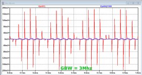
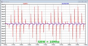
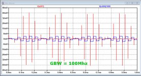
That's a good point, but it also depends on the GBW.
Images below are made with a 10V/usec op-amp, where the GBW was varied between 3Mhz and 100Mhz.
Red line is the voltage at the amp's input, and blue the 20Khz 2.8Vrms output/1000 in all three cases with a 10R resistor placed between output and 2nF cap.
The 100Mhz version shows +/-40mV at the input, whereas the 3Mhz version will be overloaded with +/-200mV peaks.
So a careful conclusion might be to use a op-amp with the following specs:
Rout open loop < 10R
Slew Rate > 10V/usec
GBW > 100Mhz.
This means that this I/V converter should not be taken too light-hearted, which convinces me more and more why a simple RC network followed by a buffer may produce a superior sound.
A S&H may have advantages, but with D/A's fast enough and S&H circuits not being without flaws, I think the "simple" RC network is a potential winner.
Hans
.
Attachments
Ken,This is what makes S/H such a nice solution. You don't need to know DAC or I/V amp slew-rates. You only need to know their settling-times, which are specified in their data sheets. By the way, for the PCM1792/94 the data sheet specified settling-time is 200nS.
I'm puzzled where you found that 200nS figure, but it seems quite likely, so thanks for providing this.
In that case, this D/A will never cause any slew rate distortion problems.
Because of repeating this several times, you seem to be a bit of an S&H adept, but this is not an easy part to make keeping the D/A figures intact and I don't think you will need it.
Question is, do you have one yourself and if so could you be so kind to show us the realization?
None of the DAC's that I have ever handled from Mark Levinson, Bel Canto, Ayre, top line Marantz (and Philips) did have this feature so even high end Dac's can live without.
Hans
I have seen clock pulses coming out of I/V opamps at several MHz. The harmonics of the clock edges go up much higher than that. However, the clock pulses are hard to see without a scope with dot averaging (high resolution mode). The one I used sampled at 5GHz to do that. The broadband noise coming out of the dac is itself another huge signal going through the opamps. The effects going on inside opamps because of all that seems likely to be hard to sim very accurately. Of course, it wasn't an NOS dac I was measuring, but still...
Just as an addition: step size at 192Khz is much smaller as at 44.1K so an I/V converter op-amp can do with lesser specs in case all input is always upsampled to 192Khz.
Hans
Hans
Kind of a shocking experience.
My Bel Canto 3.5 DAC has a LT1468 doing the I/V conversion at 192Khz.
This amp is specified as 90Mhz GBW and 22V/usec, fast enough so to think.
Although I don't know how realistic the LTSpice model is, but the output impedance seems far higher than 10R, causing to produce a spectrum that's inferior to the passive RC implementation.
So that's what I learned from this thread, I'm going to change the LT1468 into a buffer and use a passive 1K//2nF for the I/V conversion.
Anxious to find out whether this can be heard.
Hans
That's a good point, but it also depends on the GBW.
Images below are made with a 10V/usec op-amp, where the GBW was varied between 3Mhz and 100Mhz.
Red line is the voltage at the amp's input, and blue the 20Khz 2.8Vrms output/1000 in all three cases with a 10R resistor placed between output and 2nF cap.
The 100Mhz version shows +/-40mV at the input, whereas the 3Mhz version will be overloaded with +/-200mV peaks.
To complicate things further, the "linear" range of the input stage is proportional to the ratio of the slew rate to the gain-bandwidth product, so your 100 MHz, 10 V/us amplifier will slew at a much smaller error signal than a 3 MHz, 10 V/us one.
Ken,
I'm puzzled where you found that 200nS figure, but it seems quite likely, so thanks for providing this.
In that case, this D/A will never cause any slew rate distortion problems.
I just now reviewed the PCM1794A data sheet, but could not locate a settling-time figure either. Which is, indeed, puzzling because I have a diy PCM1794A DAC which I built a number of years ago, and have had that 200nS. figure in my head for a long time now. A quick search only revealed a mysteriously locked T.I. thread about it on their website, and a 2010 post here at diyAudio by member Calvin, also stating a 200nS. settling-time. See link: https://www.diyaudio.com/forums/dig...ng-feedback-caps-resistors-3.html#post2233990
Because of repeating this several times, you seem to be a bit of an S&H adept, but this is not an easy part to make keeping the D/A figures intact and I don't think you will need it.
No, I'm not a S/H adept. I'm simply intrigued by the potential subjective impact of settling-time which Frans Sessink has presented. While settling-time may, or may not be an audible issue, it takes increasing effect as the DAC's output rate increases simply because it represents an increasing percentage of the total sample area as the output rate increases. A percentage which doubles each time the output rate doubles, such as is common with OS.
For example, if a given settling-time invalidates 1% of the total of sample-periods occurring within one second at 1FS, it then invalidates 8% of the total of sample-periods occurring within one second at 8Fs oversampling. Does settling-time then become an audible issue? I don't know. As your own simulations show, however, it can become a parametric issue.
Question is, do you have one yourself and if so could you be so kind to show us the realization?
To include one would have required creation of a totally new DAC. So, including an experimental S/H had to wait. Now, that I've finally destroyed my experimental NOS DAC, I plan to include a S/H circuit for evaluation within my next DAC build. While I don't yet have all of the details worked out, I plan to utilize the rather clever S/H architecture shown in the Burr-Brown PCM56 data sheet. Page 8, figure 9. The application diagram is intended for single DAC chip L/R analog de-multiplexing of the sort I'd mentioned earlier. However, it is easily adapted for Frans Sessink style exponential-settling S/H application.
None of the DAC's that I have ever handled from Mark Levinson, Bel Canto, Ayre, top line Marantz (and Philips) did have this feature so even high end Dac's can live without.
I would tend to agree with the logic of that argument, except for the odd subjective sound issues which seem characterize typical CD playback. Since I haven't yet determined the source of of those issues, which we are investigating here, I've kept myself open to considering any commonly overlooked mechanism, such as settling-time related quantization error, which might possibly be responsible.
Hans[/QUOTE]
In late 2019 I wrote a little document about the relation between slew rate, gain-bandwidth product, open-loop output impedance and input stage "linear" range, see the attachment. As the document considers a step from 0 to I while the worst-case step is actually from negative full scale to positive full scale or the other way around, you have to fill in the step size from the negative to the positive full scale output current for I.
Attachments
- Home
- Source & Line
- Digital Line Level
- What do you think makes NOS sound different?