Hi Cortez,
sorry to take so long to get back about your queries on post111.
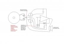
The Thiel/Zobel network (for the amplifier- not the speaker) must not be taken back to the amp PCB. This has caused many designers problem that were cured by moving the network return to the speaker terminals or direct to the power ground. Some amplifiers do not suffer from this problem and tolerate the network being taken to the PCB but it's wise to avoid the problem if you are preparing to debug a new design.
You show two grounds in your layout diagram. P with four connections and S with four connections and finally a fifth connection linking P to S. My preferred method is exactly as you have shown it. Take all the power returns direct to Power Ground (P) and take all the signal returns to Signal Ground (S). Then you have the option of how to connect them. You show a short wire link, this is OK. Some prefer to use terminal lugs for each return and then bolt them all together, this is usually OK. Keep in mind Eva's warning that mixing the P with the S returns can have a very noticeable sound (and measured) effect, i.e. changing the order of the lugs on the bolt. Personally I prefer the short wire link using lugs to separated P & S, but both ways can be made to work, i.e. making them coincident is a viable option.
Look at your time delay 2amp fuse. It should be stamped T2A indicating T= time delay, 2 =two, A= amperes. Is that enough. (F=fast, omitted =normal, I do not know the code for ultra fast).
Now back to my comment T2A seems too small for a 400VA toroid running on 110Vac mains. The starting current (without a soft start) is likely to exceed the short term limit of the selected fuse and the maximum running current could reach about 4amperes. T2A still seems too small. However I am a believer in using the smallest mains fuse that the system will run with reliably to enable close protection and thus permit fairly fast fuse blow in the event of a mishap/breakdown. If T2A works then keep it.
sorry to take so long to get back about your queries on post111.
The Thiel/Zobel network (for the amplifier- not the speaker) must not be taken back to the amp PCB. This has caused many designers problem that were cured by moving the network return to the speaker terminals or direct to the power ground. Some amplifiers do not suffer from this problem and tolerate the network being taken to the PCB but it's wise to avoid the problem if you are preparing to debug a new design.
You show two grounds in your layout diagram. P with four connections and S with four connections and finally a fifth connection linking P to S. My preferred method is exactly as you have shown it. Take all the power returns direct to Power Ground (P) and take all the signal returns to Signal Ground (S). Then you have the option of how to connect them. You show a short wire link, this is OK. Some prefer to use terminal lugs for each return and then bolt them all together, this is usually OK. Keep in mind Eva's warning that mixing the P with the S returns can have a very noticeable sound (and measured) effect, i.e. changing the order of the lugs on the bolt. Personally I prefer the short wire link using lugs to separated P & S, but both ways can be made to work, i.e. making them coincident is a viable option.
Look at your time delay 2amp fuse. It should be stamped T2A indicating T= time delay, 2 =two, A= amperes. Is that enough. (F=fast, omitted =normal, I do not know the code for ultra fast).
Now back to my comment T2A seems too small for a 400VA toroid running on 110Vac mains. The starting current (without a soft start) is likely to exceed the short term limit of the selected fuse and the maximum running current could reach about 4amperes. T2A still seems too small. However I am a believer in using the smallest mains fuse that the system will run with reliably to enable close protection and thus permit fairly fast fuse blow in the event of a mishap/breakdown. If T2A works then keep it.
AndrewT said:T2A still seems too small. However I am a believer in using the smallest mains fuse that the system will run with reliably to enable close protection and thus permit fairly fast fuse blow in the event of a mishap/breakdown. If T2A works then keep it.
I agree that T2A seems too small. However, while I hypothetically agree that it is good to select a fuse in a range that does provide max possible coverage of events, one cannot select a fuse just a little larger, the thermal cycling will wear it out even with no problems. For example if an amp has regular 3A peaks, a 2.5 A fuse may not be enough. I have blown fuses like this over the long term use of devices. Slow blow is helpful but in the end it is still relative to how hot the element gets, repetitive wear. It might be good to have at least 6A fuse in this case excepting that we don't know if the 400VA is ever realized through use, cap bank charge or saturation current.
Hi Cortez,
post108 shows a schematic to which you listed amendments.
Surely you are not saying that you now want to add another amendment, namely you do not need a mains fuse and further you did not fit one?
post108 shows a schematic to which you listed amendments.
Surely you are not saying that you now want to add another amendment, namely you do not need a mains fuse and further you did not fit one?

AndrewT:
> post108
It was just a base for the values and the inverting layout, not all the details.
> you do not need a mains fuse and further you did not fit one?
Thats true, I dont need it, so I dont have it. 😉
Mike:
Thats exactly how I wired it!
But I still dont get it, how that hum appears when I touch the heatsink.
Whats the source, and how it comes to be an input signal ?
Hi Mikeb,
re diagram in post126.
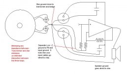
I would take the smoothing cap commons to the rectifier commons and then connect the plus and minus commons to a charging point ground (power ground) to help avoid mixing the charging pulses and attendant voltage spikes from contaminating the star ground. Then connect the power ground to the star ground.
There is absolutely no case for taking the charging pulses through the finite resistance/impedance of the star ground.
My problem is in advising where the decoupling should go. Do the two decoupling returns follow the smoothing caps to the +&- commons or to the power ground or leave them connected to the star ground. What do you think best meets your philosophy?
Any other views?
re diagram in post126.
I would take the smoothing cap commons to the rectifier commons and then connect the plus and minus commons to a charging point ground (power ground) to help avoid mixing the charging pulses and attendant voltage spikes from contaminating the star ground. Then connect the power ground to the star ground.
There is absolutely no case for taking the charging pulses through the finite resistance/impedance of the star ground.
My problem is in advising where the decoupling should go. Do the two decoupling returns follow the smoothing caps to the +&- commons or to the power ground or leave them connected to the star ground. What do you think best meets your philosophy?
Any other views?
Hi Cortez,
read Borbely and others (Leach?). He advises decoupling the heatsinks to ground. It may be your solution and maybe he explains the contamination mechanism.
WHY NO MAINS FUSE? Please explain your reasoning.
read Borbely and others (Leach?). He advises decoupling the heatsinks to ground. It may be your solution and maybe he explains the contamination mechanism.
WHY NO MAINS FUSE? Please explain your reasoning.
AndrewT
> There is absolutely no case for taking the charging pulses
> through the finite resistance/impedance of the star ground.
Could you please draw a layout about this and mark the relevant parts ?
> He advises decoupling the heatsinks to ground.
Decouple ? Or connect ?
> WHY NO MAINS FUSE? Please explain your reasoning.
I dont like to put anything in series with the primer.
And I dont feel its necessary to use a fuse here.
Its a compact chip with protection, and I take care.
Thats all...
! said:For example if an amp has regular 3A peaks, a 2.5 A fuse may not be enough.
Hmm. Make that "regular 2.5A peaks, a 3A fuse ..."
Cortez said:
Mike:
Thats exactly how I wired it!
But I still dont get it, how that hum appears when I touch the heatsink.
Whats the source, and how it comes to be an input signal ?
If you were to experiment with a magnetic probe, actually the one I built includes a headphone output, you would be amazed at the amount of mains energy that surrounds us all the time. I have to go 50 yards into the woods to get where I don't pick up any hum.
Since your body is basically a big capacitor relative to the earth, it picks quite a bit of this up. when you touch the end of an interconnect and it hums through the system you are seeing a example of this. If you ground your self to the cable shield you are no longer noisy relative to the ground reference so the noise stops (unless the system grounding is bad).
By touching the heatsink there appears to be a path back through the chip that allows this unreferenced mains hum to end up as part of your signal ground or main path. This is why I wondered what would happen if you touched the main ground with one hand and the heatsink with the other.
Grounding the heatsink would most likely fix it, but getting to the bottom of it would be nice too.
For my own curiosity I'll look at the docs and see what they say.
Mike.
AndrewT said:Hi Mikeb,
re diagram in post126.
I would take the smoothing cap commons to the rectifier commons and then connect the plus and minus commons to a charging point ground (power ground) to help avoid mixing the charging pulses and attendant voltage spikes from contaminating the star ground. Then connect the power ground to the star ground.
There is absolutely no case for taking the charging pulses through the finite resistance/impedance of the star ground.
My problem is in advising where the decoupling should go. Do the two decoupling returns follow the smoothing caps to the +&- commons or to the power ground or leave them connected to the star ground. What do you think best meets your philosophy?
Any other views?
Hi Andrew,
I would disagree, primarily because I have found that there is only one ground and that it has to be as close to the transformer and as low an impedance as possible. I you think in terms of a power loop that leaves the positive (or negative) side of the transformer, it eventually ends up back at the opposite end of that winding. There is no separate reference for the signal returns, charging currents or noise filtering. If there are separate ground islands (as I'm interperting your suggestion) there has to be a connection that brings it all back to the transformer and this would be the weak point.
I create a star point and then return the individual loops back to that point. If it's beefy enough (I believe that's a technical term somewhere) there will be little drop or variation or interference between the various demands of the amp.
If you examine the images I've posted early on you will see the way that I've implemented this. You can note that I take my copper buss right to the windings coming out of the transformer directly to the star which is also bonded to the chassis. from there there are separate loops as required.
The power rails are handled in a similar manner as well as the board layout. It's the loop that matters.
As for the decoupling caps, they are part of the power supply loop and should go back to the filters. I don't need or have any. The heatsink is grounded at on point to the chassis, which is also visable. The mounting screws are isolated, which also allows the sink to float as it expands and contracts.
Just a suggestion, something at little different to tryout.
Mike.
Hi Cortez,
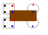
here's my slightly modified grounding showing the smoothing caps connected straight to the rectifier. Then the rectifiers connected to the new Power Ground and finally the Power Ground to the Central Star Ground (clean ground).
I cannot countenance the omission of a mains fuse.
For the safety of yourself and your house wiring so really must reconsider.
Attachments
Re: just quickly
If you have an isolated power board (separate from amp board), it's splitting hairs, shouldn't matter if the ground return is a cm or two closer to the rectifiers or caps. Hypothetically though, you want it most upstream from the amp board, nearer the rectifiers. The impedance of the ground *plane* is low but it and the connecting cabling to the amp board are then what isolation you have to return further way from amp.
Mainly, you don't want to dump that into the signal ground path so the reasonable compromise for some is the star ground on an integrated amp/power board.
Cortez said:Maybe a ground plane is the best solution here too, like this.
The only question is, where to put the returning ground wires,
near to the rectifiers, or near to the caps, or in the middle...
If you have an isolated power board (separate from amp board), it's splitting hairs, shouldn't matter if the ground return is a cm or two closer to the rectifiers or caps. Hypothetically though, you want it most upstream from the amp board, nearer the rectifiers. The impedance of the ground *plane* is low but it and the connecting cabling to the amp board are then what isolation you have to return further way from amp.
Mainly, you don't want to dump that into the signal ground path so the reasonable compromise for some is the star ground on an integrated amp/power board.
Hi Cortez,
I have never recommended tying a star ground into that common plate arrangement.
There is an exception that works;- keep the plate for the Power Ground ONLY.
Attach a bolt through the plate and attach terminal lugs to one side only starting with the highest current consumers (speaker return) and follow with all the dirty returns. Then attach the clean returns with the final one being the lowest current (input RCA ground). Do not attach the Safety Ground (earth) to the same side as the clean returns. You can use the other side of the same bolt provided you use a separate nut to permanently fix the earth and then all the other returns after that permanent nut. Personally, until convinced by MikeB, I would not attach the earth here.
Do not mix the order by putting some clean returns in between dirty returns (Zobel, decoupling, etc.).
The bolt is effectively a low impedance very thick wire and the lugs increase the cross sectional area.
DO NOT scatter returns around the Power Ground plate. This method guarantees different voltages at each attachment point.
AndrewT said:Hi Cortez,
here's my slightly modified grounding showing the smoothing caps connected straight to the rectifier. Then the rectifiers connected to the new Power Ground and finally the Power Ground to the Central Star Ground (clean ground).
Hi AndrewT,
I'm not disagreeing here to be a jerk, more because I have found this to work differently.
Firsts I don't see the reason in connecting the filters together because there should be no currents between them.
Second, your logic concerning the charging currents is sound if that is all that is happening. What these traces also have to deal with is the output stage sinking power reflected back from the load, essentually backwards through the supply filters , once again , to ground. These can be substantual at high power levels. The wires between the filter/bridge combo that you have added now reflects these currents and adds them to the ground reference to the input and feedback.
I don't have time to modify the drawing now, but can discuss more later.
Mike.
Mike:
> By touching the heatsink there appears to be a path back through the chip
Ok, but along the whole chain either through the trafo ?
Or if I had a PS with battery, touching the heatsink would cause humm as well ?
> This is why I wondered what would happen if you touched the
> main ground with one hand and the heatsink with the other.
I will try !
> Grounding the heatsink would most likely fix it
Also...!
AndrewT:
> I have never recommended tying a star ground into that common plate arrangement.
I know, I recommended it. 🙂
> Do not mix the order by putting some clean returns in between dirty returns (Zobel, decoupling, etc.).
I would put the speaker GND near ro the rectifiers, and the signal GND near to the the main caps.
I think with a layout like this, we have a good grounding in both cases:
when the power is provided by the caps:
the signal gnd is near to the caps, so the high speaker current doesnt affect it much
when the power is provided by the trafo:
the signal gnd has a very low impedance path to the rectifier too through the plane,
so they 2 havent a common path just as its unavoidable, in opposite
with a conventional arrangement, when the main ground is in the
middle of the caps, cause in case the caps are charged, the ground
is rather at the rectifier, and the ground path is common for:
- charging current
- speaker ground current
- signal ground current
Or maybe we just should to use a lug in the exact middle of that plane,
and connect both ground to this point ?
> Firsts I don't see the reason in connecting the filters together
> because there should be no currents between them.
But the voltage level can maybe swing on that point.
> output stage sinking power reflected back from the load essentually
> backwards through the supply filters , once again , to ground.
> The wires between the filter/bridge combo that you have added now reflects these
> currents and adds them to the ground reference to the input and feedback.
I guess this is a very interesting thought !!
Imagine that the speaker stored some energy in a capacitive way, and after a while
it radiates this energy back to our system, and of course in the ground too.
But if the PS cant receive this completely, this means a finite but existing impedance
at the caps, so this current will appear in the signal ground.
Whats your opinion ?
- Status
- Not open for further replies.
- Home
- Amplifiers
- Chip Amps
- What distance should a toroidal be from the audio circuit?