The Image in post 23 is where I started before this got off on why it won't work and safety grounding. It should answer your question.
The whole point was to use a plane, my suggestion for simplicity was the chassis (but now I know I'll be sent to jail for that 😉 ), or as I'm currently doing, using a copper plane (which could be isolated from the chassis) to connect the input connector back to the power supply reference ground. The amp circuitry is grounded to the connector. That's it.
The low-z over a broad bandwidth is what's important to provide a proper clean reference for the circuit. In most cases you have no control over the source grounding, the interconnects or the noise invioronment the system is in. You can only try to keep all of the noise pickup and interchassis currents out of the amplifier signal grounds. This approach does do that.
I appologize for the complicated mess this discussion turned into, but it's primarilly the downside of drive by computing. The lack of visual clues and the ease of misunderstanding that happens because of it. The same discussion over a cup of coffee with a napkin to draw on would have taken a few minutes.
I wasn't understanding where the questions were coming from (the problem with the chassis, saftey, circuit ground) (to my mind there is only one important ground) and the more I tried to answer what I what I thought was being asked, the more complicated my answers got; trying to show the bigger picture and how it fit in to help it make sense.
Mike
> I forgot the attachment.
Ok then, thats why I didnt understand you...
> The Image in post 23 is where I started before this
> got off on why it won't work and safety grounding.
Ok so thats your advanced layout. I thought thats just one, and there is a second after that.
Now it's all clear I guess, so thx ! 😉
> The same discussion over a cup of coffee with a napkin to draw on would have taken a few minutes.
I completely agree with that, forum is very confusing sometimes...
Hi Mikeb,
is that last diagram in post100 what you having been trying (unsuccessfully) to describe?
If so, then it shows the safety ground (earth) completely separate from the audio ground.
is that last diagram in post100 what you having been trying (unsuccessfully) to describe?
If so, then it shows the safety ground (earth) completely separate from the audio ground.
Diagram in post 100 - Mike reproduced Cortez's diagram but included resistors to illustrate problems with it.
Here is my current GC layout. Its basicly everything OK, but
if I touch the heatsink on the top, a little humm appears.
Who knows how this works? Maybe in a capacitive way starting from the trafo,
and going all along the hole circuit, and then to me and back to the earth ?
(Otherwise nothing is shielded and earthed in this layout)
if I touch the heatsink on the top, a little humm appears.
Who knows how this works? Maybe in a capacitive way starting from the trafo,
and going all along the hole circuit, and then to me and back to the earth ?
(Otherwise nothing is shielded and earthed in this layout)
Attachments
AndrewT said:Hi Mikeb,
is that last diagram in post100 what you having been trying (unsuccessfully) to describe?
If so, then it shows the safety ground (earth) completely separate from the audio ground.
Andrew,
I've been thinking about this safety ground thing. It seems to me that a safety ground and system ground should be able to coexist without too much interference. I'm wondering if you (or someone) can post an example of how a basic
source/amp/preamp system might be hooked up in Europe. Nothing elaborate. Primarilly the connection of the SG relative to the signal/power supply grounds. I sort of know how it would be but then I don't want to assume... I'd like to experiment with this and see what happens.
Thanks, Mike.
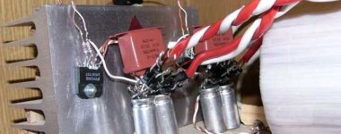
Cortez said:Here is my current GC layout. Its basicly everything OK, but
if I touch the heatsink on the top, a little humm appears.
Who knows how this works? Maybe in a capacitive way starting from the trafo,
and going all along the whole circuit, and then to me and back to the earth ?
(Otherwise nothing is shielded and earthed in this layout)
Cortez,
I assume that GC refers to the Gain Clone amplifier I've read reference to in a few threads? Is there a schematic posted that is similar to the execution of your amp that I can look at? It's hard to comment without seeing what's happening in the input stage and the implementation of bypass/decoupling caps etc.
I see that you are using two bridge rectifiers in your supply. I've seen this a number of times and am wondering why one would use this instead of one bridge. I'm using it in one of my preamps, but then I was just copying another supply design that used it. Is there a reason that has been discussed that you are aware of?
Regards, Mike.
> a safety ground and system ground should be able to coexist without too much interference
A safety earth has a long wire in the walls paralell to
a high voltage line, so its a great antenna, isnt it ?
If yes, why should we connect it, to our clean signal ground ?
> Is there a schematic
Yep, attached. But my taper is 50k and dont have an input cap.
Just two 33k and one 1M resistors is in this layout, no 100n on
the non-inverting input, and no 0R22 on the output.
> two bridge rectifiers in your supply
> am wondering why one would use this instead of one bridge
Dont wonder, try it ! 😉 Its simple, it sounded better to me.
I have a very sensitive fostex speaker, it shows everything, but
of course the difference wasnt so huge... You really should try it.
Attachments

Hi,
re Cortez ground layout in Post108.
If one should decide to add a Thiel or Zobel network to the amp output , the return leg of the network should connect to the speaker return or direct to the power ground(P).
The short wire between P and S can be made co-incident.
A third ground either remote from P & S and nearby is for the Safety ground. The Safety ground can connect to P via a disconnecting network. NO PART of the AUDIO ground system, including the RCA input grounds should connect to the safety ground.
Cortez,
a question, how big is your transformer? and what type Toroid or EI? Just the T2A seems a little small for a toroid.
> If one should decide to add a Thiel or Zobel network to the
> amp output , the return leg of the network should connect
> to the speaker return or direct to the power ground(P).
Its a question or a statement ? 🙂
I dont know surely, someone says to the speaker, someone that right to the amps output.
Who knows, maybe we could put on both place... 😀
Maybe right at the amp's output is the better way.
> The short wire between P and S can be made co-incident.
Sorry, I dont get it.
> how big is your transformer?
400VA toroid.
> T2A seems a little small for a toroid
Whats T2A ?
Cortez said:> a safety ground and system ground should be able to coexist without too much interference
A safety earth has a long wire in the walls paralell to
a high voltage line, so its a great antenna, isnt it ?
If yes, why should we connect it, to our clean signal ground ?
> two bridge rectifiers in your supply
> am wondering why one would use this instead of one bridge
Dont wonder, try it ! 😉 Its simple, it sounded better to me.
I have a very sensitive fostex speaker, it shows everything, but
of course the difference wasnt so huge... You really should try it.
It's all becoming clear... There is no connection between the safety ground on the chassis and the signal ground! In my experience with audio equipment using a third wire safety ground, it was always taken to the chassis and connected to the power supply ground, sometimes directly or sometimes through a low value resistor. I'm not sure about today's audio equipment since I'm no longer in the business and it really doesn't matter to me. But you can now understand why I was getting confused.
I do have a question as to how shielding is accomplished since in order for a shield to be effective it must be referenced to the signal ground, but I'll assume it's accomplished separately and the chassis is not used.
I'll take a bit of time later to study the drawing and the picture. one question though, is the heatsink grounded and if so where relative to the chip. I'm also curious about the chip mounting plate and if it's grounded internally. to the chip ground. I have a data sheet at home.
Regards, Mike.
MikeBettinger said:
one question though, is the heatsink grounded and if so where relative to the chip. I'm also curious about the chip mounting plate and if it's grounded internally. to the chip ground. I have a data sheet at home.
There can only be 3 possibilities for the 'sink and I'm not so sure it matters relative to noise pickup (except as mentioned at the end).
- Uninsulated chipamp (chip) where the 'sink tab is not at ground. For example LM3886 has it's tab at V- rail as does LM3875. Cortez' post 109 shows the LM3875TF though, the insulated package. I suspect though, if you took a drill and drilled through the epoxy/plastic/whatever, you'd hit the tab and find it's still at V- rail. So the 'sink sits at V- unless an insulator pad and screw are used.
- Insulated chipamp package, tab, where the 'sink makes electrical contact with nothing significant, fully insulated.
- Insulated chipamp package where the 'sink makes contact with the chassis... which is then at earth or signal ground (if not both as being discussed previously).
So it may not matter about the 'sink? That is, except it can be handy to ground it to provide the shielding if/when rest of chassis is, too and it's located such that it might be of benefit to do it.
> There is no connection between the safety ground on the chassis and the signal ground!
Here on this pic:
http://www.diyaudio.com/forums/attachment.php?s=&postid=902542&stamp=1146155001
The signal ground is directly connected to the safety earth through the chassis, inst it ?
> is the heatsink grounded
No, it isnt, thats what I will try next time.
Here on this pic:
http://www.diyaudio.com/forums/attachment.php?s=&postid=902542&stamp=1146155001
The signal ground is directly connected to the safety earth through the chassis, inst it ?
> is the heatsink grounded
No, it isnt, thats what I will try next time.
So it may not matter about the 'sink? That is, except it can be handy to ground it to provide the shielding if/when rest of chassis is, too and it's located such that it might be of benefit to do it. [/B][/QUOTE]
The tab has capacitance related to the surface it is mounted to, this can couple the hum pickup from his body through to the chips internal ground. It's the same mechinism behind touching an open connecting cable and hearing a hum through the system. I believe I read that a TO-247 package has 10 -20 pf when mounted, I'd have to dig through my files for an exact number. To test this he could ground himself to say an input ground and then touch the heatsink. If it diminishes then the noise is definitely a grounding issue.
I'd put a voltmeter between the two points and make sure their at zero before trying this, although they should be if the tab is insulated.
I'm still at work so I haven't looked real close at the images yet.
Mike.
Cortez said:> There is no connection between the safety ground on the chassis and the signal ground!
Here on this pic:
http://www.diyaudio.com/forums/attachment.php?s=&postid=902542&stamp=1146155001
The signal ground is directly connected to the safety earth through the chassis, inst it ?
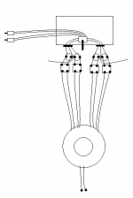
#1 is is connected to the chassis (although I now realize I didn't spell it out) and the SG is connected at #11. Also in the preamp #4 is connected to the chassis and #12 is the SG connected as well.
In your image there is no connection, or am I confused again?
Mike.

Hi Cortez,
Couple of thing on circuit design you might want to try. First is the gain. Do you need 30dB of gain? Fostex driver are very efficient so you do not need that much gain. With less forward gain you will have better sound. I've found 20-25 dbs works well. I've used 20dBs on my rear loaded Lowthers sounded very good. The higher you run the gain the more noise and grunge you amplify. The next thing is the Zobels. I found that the Zobels with the Lowthers were not the best sound. I found to get the best sound with a high efficency speaker you have to use the highest quality power supply cap you can afford. I would recommend using a Blackgate 1000mf standard to start. Any of the better grade Blackgates will soud better than the standard. The main advantage of the Blackgates are they are made of packed carbon and have next to no inductance which isa big advantage with chip amps. If you have to use something other than a Blackgate then you may need a Zobel. This you will have to determine sonically.
You need to use smaller resistor values for the feedback. 1M and 33k are to high off value. Smaller values sound much better. Try 249 and 10k. This gives a gain of 25dB. Which will give you a very good sound. The next thing you need to change is the volume control pot. A 10k pot will work very nicely. The last thing I would scrap is the 4.7uf input cap. All cd players are cap coupled out so there is no chance of getting any DC. This wiill sound the best but it is your decision. The 1uf is a bit large. Try something around .33ufd.
Andy
MikeBettinger said:The tab has capacitance related to the surface it is mounted to, this can couple the hum pickup from his body through to the chips internal ground. It's the same mechinism behind touching an open connecting cable and hearing a hum through the system. I believe I read that a TO-247 package has 10 -20 pf when mounted, I'd have to dig through my files for an exact number. To test this he could ground himself to say an input ground and then touch the heatsink. If it diminishes then the noise is definitely a grounding issue.
I'd put a voltmeter between the two points and make sure their at zero before trying this, although they should be if the tab is insulated.
It could be important to consider what specific parts and mounting were used to achieve 10-20 pf.
His being the TF package, may have a bit thicker than a mica insulator. I find it hard to believe that there could be `10-20pf through a silicone mat type though, being quite a bit thicker.
Why do we care though if it picks up hum if he's touching it? That's not a grounding "issue" per se, because it's not a problem unless the amp is meant to run with operater holding the heatsink. Similarly we could argue that if he's touching some chipamp pin and it picks up hum that this is a problem but we can't very well ground those...
! said:
Why do we care though if it picks up hum if he's touching it? That's not a grounding "issue" per se, because it's not a problem unless the amp is meant to run with operater holding the heatsink.
I don't really care, but it is an indication of something not being right. Why would someone spend $15 on a resistor when a .05 cent part will do the same. I'm just responding as I feel the compeled, it's interesting and fun and I have 30 years of (active) experience to draw on.
Mike.
Mike:
> this can couple the hum pickup from his body through to the chips internal ground
But its so obvious that the 50Hz mains can go through the whole "trafo,
diodes, caps, GC, heatsink, me"-chain, and cause an audible humm ?
> It's the same mechinism behind touching an open connecting
> cable and hearing a hum through the system.
I just dont get, where this "humm circuit" is exactly created.
> In your image there is no connection, or am I confused again?
Nope, on my there isnt any connection between any ground and
the safety earth, its completely separated, but we talked about
your layout, and there is a connection, namely 0R, the chassis.
Or I am confused now ? 😀
Andy:
Thank you for your tipping, will try these !
!:
> Why do we care though if it picks up hum if he's touching it?
I am just interested in this phenomenon, thats all 🙂
- Status
- Not open for further replies.
- Home
- Amplifiers
- Chip Amps
- What distance should a toroidal be from the audio circuit?