So before I get a bunch of replies that essentially boil down to "It depends", let me explain:
I want to make up a few PCB's to play around with different amplifier designs, and I want it to accommodate a wide variety of topologies, rather than a specific design. So for example, I want to build a preamp stage with the ability to add/remove/adjust various components (think adjustable cathode bias, removeable bypass caps, variable power supply to adjust plate voltage) in order to basically build a test bench to start getting a better feel for how various changes affect the tone of the amp. I want to essentially put board to board connectors on each board so I can basically put them together like puzzle pieces to quickly try out different designs to see what I like. The issue is that I don't know what current rating those connectors need to be. Right now, I'm thinking that each 12AX7 will have the following connectors:
Signal Input
Stage 1 Output/Stage 2 input
Output
Heater
Plate voltage
So what current ratings would you be specing for something like this? Right now, this question pertains to the preamp stages, and I'm targeting 12AX7's just because they seem pretty common, but I might want to try other tubes that have similar pinouts in the future. If you have suggestions for a similar thing with power amps ( was thinking about combining the PI and power tubes on one board), that would be great, too.
Thanks!
Heater supply is shown on the datasheet, you can look at that.
The very most the plate can suck is B+/Rp. Say 300V and 100k. 3mA max IF the tube were a dead short. That's not interesting. In general about half the B+ appears across the resistor, a "fair fight". So 1.5mA. Or 3mA if you expect shorted tubes.
The output current must be less than the tube current.
The input current to an audio preamp tube is much-much less than tube current.
I don't think you can buy connectors this small.
The cold resistance of a 12AX7 filament is approximately . . .
12 Ohms from pin 4 to pin 5 (series filament for 12.6V).
6 Ohms from pin 4 to pin 9; and 6 Ohms from pin 5 to pin 9 (parallel filament for 6.3V, is only about 3 Ohms cold).
When you first turn the power on . . .
You get about 1 Amp inrush for series filaments,
And you get about 2 Amps inrush for parallel filaments.
The 12AX7 data sheet does not tell you this.
That is a lot more than the 150mA for hot series filaments,
and 300mA for hot parallel filaments.
Do not use either super narrow super thin PCB traces, or super low current sockets, to power Cold filaments (unless you are using some kind of very good soft start circuit on the filaments).
Just my opinions
Just about any 0.1 inch pitch connector/header will be more than adequate. If you want to go for overkill use 0.2 inch pitch terminal blocks.
Cheers
Ian
Cheers
Ian
Good catch.The cold resistance of a 12AX7 filament is approximately . . .
12 Ohms from pin 4 to pin 5 (series filament for 12.6V).
6 Ohms from pin 4 to pin 9; and 6 Ohms from pin 5 to pin 9 (parallel filament for 6.3V, is only about 3 Ohms cold).
When you first turn the power on . . .
You get about 1 Amp inrush for series filaments,
And you get about 2 Amps inrush for parallel filaments.
The 12AX7 data sheet does not tell you this.
That is a lot more than the 150mA for hot series filaments,
and 300mA for hot parallel filaments.
Do not use either super narrow super thin PCB traces, or super low current sockets, to power Cold filaments (unless you are using some kind of very good soft start circuit on the filaments).
Just my opinions
Ok, so sounds like everything should be pretty low current if I make sure to turn on the heater before power, but I should probably design the power connectors/traces to be 2 amp tolerant in case my ADD brain forgets to turn on the heaters at some point. That's exactly what I was looking for, so thanks everyone.
Are these assumptions roughly the same for power tubes, as well?
I'm kind of excited for this project, so I appreciate all the help.
Are these assumptions roughly the same for power tubes, as well?
I'm kind of excited for this project, so I appreciate all the help.
First off, ask yourself what is the biggest tube that I will ever stuff in this thing and add some margin. That way you won't be doing it over again next time a bigger power tube comes around.
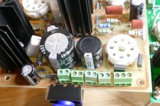
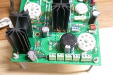
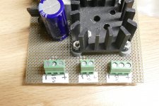
I have been making vacuum tube prototype boards for 20+ years. I use the green connectors seen here. The pins are on 200 mil centers so they can be used on perf board too. They have seen 5 amps or more of heater current if the screws are tight. If stuffing more than 350 volts into one, leave an unused pin between any two terminals with more than 350 volts between them. They are used in my finished boards too. There is an unused pin between the HV secondary leads on the power transformer in the amp boards since they see 750 volts or more. The three pin connector has the middle pin unused. To connect two boards directly together I stick short pieces of #14 wire into each active pin, tighten the screws, then insert the whole "row of nails" into a matching set of connectors on the second board.
I get them cheap here. TER 202 (2 pin) and TER203 (3 pin) can be snapped together to make any length except a single pin. Digikey and Mouser have similar connectors for more money.
https://www.allelectronics.com/category/755/terminal-strips/1.html
Attachments
HadMatter,
I was not sure what you are saying in your Post # 6.
If you connect a 12.6V secondary or a 6.3V secondary to a cold 12AX7 series filament, or a cold 6.3V parallel filament respectively . . .
you will get inrush currents (start up / warm up currents) of about 1 Amp and 2 Amps respectively.
Power tubes do have lower resistance filaments when cold, than when warm.
A 300B filament is about 1 Ohm when cold.
When the 300B filament warms up, 5V at 1.25 Amps, it is 4 Ohms.
I used a 6.3V filament, Schottky bridge, 20,000 uF cap, about a 2 Ohm series resistor, and another 20,000 Ohm cap.
The 6.3V secondary was actually closer to 6.7V or 6.9V, and the 2 Ohm series resistor made the DC to the filament be 5V.
The 2 Ohm resistor not only dropped the DC Volts to 5 Volts, it made for a soft start filament circuit.
Cold filament 1 Ohm in series with 2 Ohm resistor divides the voltage, and limits the inrush current at power on.
Warm filament of 4 Ohms in series with 2 Ohm divides the voltage, and causes a steady 5VDC on the filament.
Using a soft start like the above, limits the start up current.
But instead, if you connect a 5V secondary that has a very high current rating directly to a 300B,
it will cause a 5 Amp inrush current to the 300B filament. That is a quick warm up!
Who knew?
Last edited:
If you are making up boards, allow for the difference in heater pins between the 12A*7 types and the 6092/ECC88 types. Both bases are very popular. You can look up the details on Franks tube pages. Note that the Russian 6N2P is a 12AX7 equivalent with a 6092/ECC88 type base.
I use 50 mil traces for B9A preamp tube heaters.Ok, so sounds like everything should be pretty low current if I make sure to turn on the heater before power, but I should probably design the power connectors/traces to be 2 amp tolerant in case my ADD brain forgets to turn on the heaters at some point. That's exactly what I was looking for, so thanks everyone.
Are these assumptions roughly the same for power tubes, as well?
Power tubes is a whole different ball game. Heater currents are much higher as are HT voltages.
Cheers
IAn
For preamp tubes 0.5mm is good enough. For a tube like a 6AS7G with 2.5A draw, I use 1.5mm or 2mm. All wire connectors I use are 5mm spacing. Design the boards in metric.
No, no, no, design in imperial.. Design the boards in metric.
Cheers
Ian
No, no, no, design in imperial.
Cheers
Ian
Simple really...
2mm = 5/64ths
3.5mm = 9/64ths
4mm = 5/32nds
4.5mm = 11/64ths
etc. etc. until your head hurts......
On the other hand
20 mil ~ 0.5mm
40 mil ~ 1mm
100 mil ~ 2.5mm
No head hurting required.
Cheers
IAn
20 mil ~ 0.5mm
40 mil ~ 1mm
100 mil ~ 2.5mm
No head hurting required.
Cheers
IAn
To me, 2mm is 0.0787 inches. 🙂
USA, Liberia, and Myanmar are the only three countries on Earth that still use Imperial. It's archaic IMHO. Parts and almost everything else on Earth is designed in Metric so why beat a dead horse?
Imagine computer chips designed in imperial? 5 nanometres becomes 1.9685e-7 inches...
Even a JLCPCB will convert to metric when you upload the Gerber.. 100mm is 3.93 inches. A 4x4 inch board costs substantially more money.
Last edited:
Sorry but on PCBs use "Imperial" for two very good reasons:
1) I wrote "Imperial" between quotation marks (") because although remotely based on some forgotten King´s thumb width, it is actually a DECIMAL scale, no fractional whatsoever.
A Mil is 1/1000th of an inch and what you will find in most datasheets of what we use.
In fact, most show both, notice Mils are round numbers and Metric by it is usually a weird approximation, requiring extra digits ... and still missing.
Now THAT is a real grey cell breaker.
Notice that although dimensions are given in mm, they are clearly translated Imperial Mil ones.
Even in modern SMT SOIC packages, and coming from Toshiba (Japan, which IS Metric), dimensions are clearly Imperial Mil based:
2) MILS are the de facto component size units since forever (at least 60/70 years) and are as DECIMAL as they come: 1000 mils to an inch.
Being the de facto standard, no head aching at all.
Metric Electronics are the new kid on the block, apply to (some) microprocessors and all that junk, specially because they are being designed in Japan, Korea, Taiwan , China, all of which are Metric.
But that´s important in the Digital World.
For us interested in the ancient and rapidly becoming obsolete world of Analog Audio, Mils rule.
3) simple: just-read-the-datasheets 😉
4) I can understand that from some noobs, weaned on Arduino and whose first ever contact with PCBs is free Eagle, set to Metric (ugh!), Metric seems to be the one and only vision of the PCB World ..... but for us who have been designing and making PCBs for decades, from India Ink drawings on tracing paper to Bishop Graphics tapes and pads to 2:1 printed drawings later reduced photographically to normal size on high contrast film to 1:1 Laser printing on transparencies which could be uses as-is to burn boards or silkscreen to direct printing on copper, Mils are the units of choice; any other a needless complication.
Last edited:
There are a lot of parts in existence that were originally based on Imperial, and these still hang around to no useful purpose. They will probably be phased out gradually.
But look at any common metric/imperial ruler and you'll see the imperial scale in fractions. That's just a weirdo place one doesn't want to go to in a lucid frame of mind, like a garden drinks party at the North Pole.
interesting facts from JM Fahey above, though.
But look at any common metric/imperial ruler and you'll see the imperial scale in fractions. That's just a weirdo place one doesn't want to go to in a lucid frame of mind, like a garden drinks party at the North Pole.
interesting facts from JM Fahey above, though.
Interesting info, JM. However when I look at part sizes, I see for example, a capacitor that is 18mmx35mm with a 7.5mm lead spacing. No inperial there (except weird decimals and fractions).4) I can understand that from some noobs, weaned on Arduino and whose first ever contact with PCBs is free Eagle, set to Metric (ugh!), Metric seems to be the one and only vision of the PCB World ..... but for us who have been designing and making PCBs for decades, from India Ink drawings on tracing paper to Bishop Graphics tapes and pads to 2:1 printed drawings later reduced photographically to normal size on high contrast film to 1:1 Laser printing on transparencies which could be uses as-is to burn boards or silkscreen to direct printing on copper, Mils are the units of choice; any other a needless complication.
Do you still use a rotary dial telephone? 😀
It's great that people like yourself have been making PCBs for decades, but that's no excuse to stagnate on outdated measurements IMHO.
Even GM uses Metric nuts and bolts on their cars these days
As an aside, when I was growing up, I measured my weight in pounds and my height in feet and inches. Now I'm 85 kg, and 1,77M tall. 🙂
I haven't switched to kW from HP yet though.
I'll probably always continue to use what I've always called "decimal fractions," which, I guess, are really Mils with the decimal point three places to the left.
5/8" = 0.625" = 625Mils
7/8" = 0.875" = 857Mils
3/32" = 0.09375" = 93.75Mils
etc...
5/8" = 0.625" = 625Mils
7/8" = 0.875" = 857Mils
3/32" = 0.09375" = 93.75Mils
etc...
This is simply not true. Yes there is a web site that says it but that does not make it true. Many countries still use a mixture of metric and imperial units. The UK, for example, has been like this for a long time. Roads distances are still measured in miles, milk and beer are sold by the pint, and area is measured in acres and PCB software is based on thousandths of an inch. All wood sizes, though quoted in mm are converted from their imperial originals. Rotary switches still have quarter or one eight in shafts, DIL ICs pins are all 100 mil apart and a regular dip is 300 mil wide. Nearly all SMT components lead spacings are imperial - I don't see that changing any time soon. Trouser waist and inside leg ,remeasurements are still in inches, , chest size for jackets and hat sizes are all imperial too. The list goes on and on.USA, Liberia, and Myanmar are the only three countries on Earth that still use Imperial.
Cheers
Ian
- Home
- Amplifiers
- Tubes / Valves
- What are the maximum currents I can expect to power a 12AX7?