This graph seems to advocate for minimum baffle...🙄
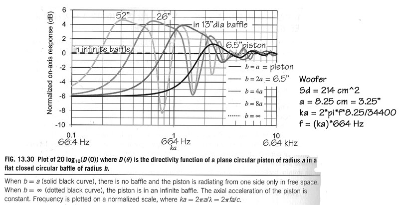
But it is only true on axis, which makes me think that the worst baffle is a baffle oriented towards the listening position. The more off axis the best, width and driver positionning, edges rounding, etc... being secondary.
Acoustics & Mechanics
Guess Fitz won't agree...😀
But it is only true on axis, which makes me think that the worst baffle is a baffle oriented towards the listening position. The more off axis the best, width and driver positionning, edges rounding, etc... being secondary.
Acoustics & Mechanics
Guess Fitz won't agree...😀
Last edited:
As I understand it, diffraction is from going from a 2*pi (hemisphere off a flat surface) space to a 4*pi space (3D sphere). If you mount in a wall, you're always in a 2*pi space so you avoid diffraction. Otherwise you have some degree of diffraction.
The diffraction can be easily measured as it causes constructive (peaks) and destruction interference (nulls) on top of the normal response. So it looks like more ripple or bumps.
You may (or not) be able to hear it depending on the amplitude and frequency. I think most people want a flat freq response so they try to minimize diffraction.
But can it be measured by the human ear.. and if so; who's?
As I understand it, diffraction is from going from a 2*pi (hemisphere off a flat surface) space to a 4*pi space (3D sphere).
That is the description of diffraction at lower frequencies (relative to the baffle size), and is usually called baffle step. At higher frequencies diffraction exhibits itself when a sound wave traveling along the baffle reachs a discontinuity and reradiates crateing an additional source for the sound.
dave
This graph seems to advocate for minimum baffle...🙄
But it is only true on axis, which makes me think that the worst baffle is a baffle oriented towards the listening position. The more off axis the best, width and driver positionning, edges rounding, etc... being secondary.
Acoustics & Mechanics
Guess Fitz won't agree...😀
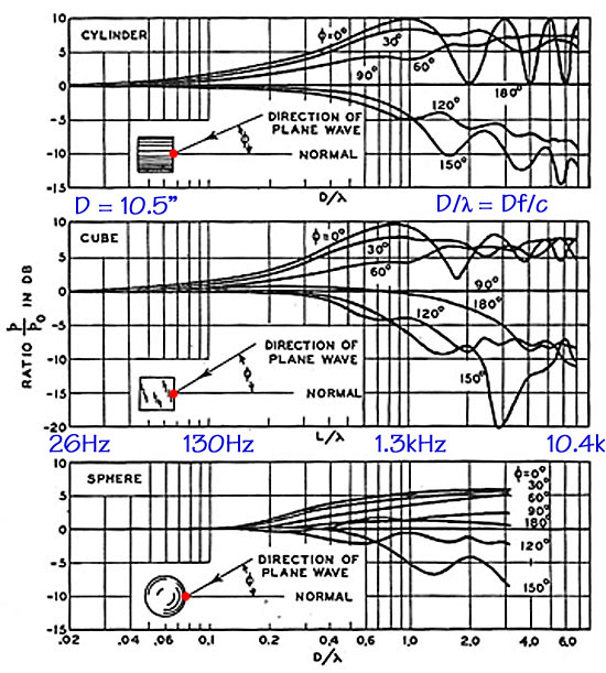
Looks like the best is sphere - on your last graph. Like B&W. But for DIY, it's kind of hard to make. Maybe I'll try a semi-round thing.
To nigelb63 -Yep, there will be diffraction ripples in every tweeter's response. But the (in)sensitivity of hearing masks them quite easily above 6kHz ( adapted from Kreskowsky)
We humans are most sensitive to sound deviations at range between 2-5kHz, which is exactly where most M-T xo's are and also where worst (read first order) diffractions of conventional hifi-loudspeakers are.
Hearing range - Wikipedia
We humans are most sensitive to sound deviations at range between 2-5kHz, which is exactly where most M-T xo's are and also where worst (read first order) diffractions of conventional hifi-loudspeakers are.
Hearing range - Wikipedia
Last edited:
But can it be measured by the human ear.. and if so; who's?
Have a look at the graphs from @GDO, you can see the magnitude of the ripple starting at low freq and continuing up as a function of baffle dimension and shape. In some cases it's >+/-3db and you can hear that. Some baffles (like narrow rectangle) have reducing amplitude of ripple with increasing freq (#wavelengths w.r.t baffle dimensions).
To convince yourself, take a 20 (1/2 octave) or 30 band (1/3 octave) equalizer (like EQ APO) and modify one of the bands by +/-3db and see if you can hear it. I can.
Mmm ... Averaging for listening window , too bad practice, what for, hiding the naked truth?😕
Those that I linked, are not averaged but 0¤ ( I edited text of first post)
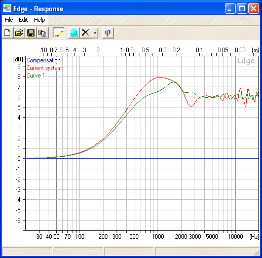
About baffle dimensions, a round baffle with driver in the center is the worst scenario! I has constant distance from radiator to edge. A square or preferably rectangular with offset radiator is best compromise. Do a simulation, then move the mic sideways to study how response changes at different angles!
Try it here, download The Edge!

Last edited:
Na... Off axis sims with the Edge are NOT reliable at all: total waste of time...
Regarding the graphs posted ( old material by Olson and others recycled for the fun by Linkwitz for its quite enjoyable Fitz platonic dialogues...😛), these are obviously extreme cases, and rectangular boxes with or without rounded edges are much more civilized. But the argument pro minmum baffle remains valid...
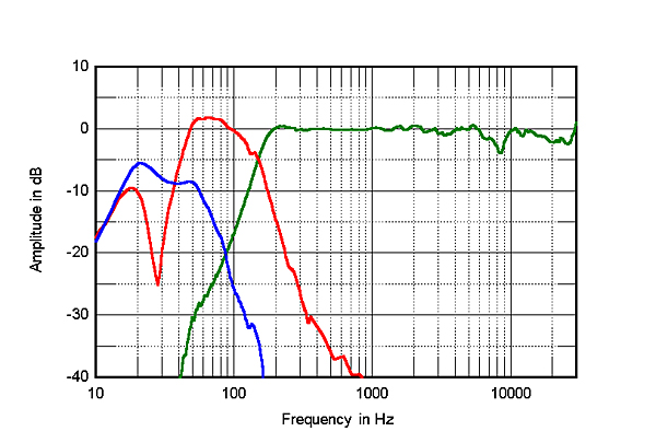
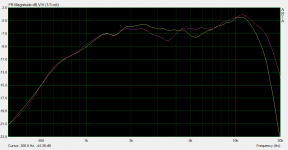
A more realistic example is how a Morel tweeter measures on a cabinet of mine on axis and at 30º off, the dip caused by diffractions around 3khz on axis moving practically one octave up at 30º.
Regarding the graphs posted ( old material by Olson and others recycled for the fun by Linkwitz for its quite enjoyable Fitz platonic dialogues...😛), these are obviously extreme cases, and rectangular boxes with or without rounded edges are much more civilized. But the argument pro minmum baffle remains valid...
A more realistic example is how a Morel tweeter measures on a cabinet of mine on axis and at 30º off, the dip caused by diffractions around 3khz on axis moving practically one octave up at 30º.
Attachments
Last edited:
I got a rather good match between EDGE sims and measurement of the real thing, but that might have been pure luck... then again, when it's correct on-axis why should it err off-axis? Within limits, of course.Na... Off axis sims with the Edge are NOT reliable at all: total waste of time
Last edited:
At 30º you no longer need to bother with a sphere, all are smooth enough
Yes, but I would prefer to listen to on-axis as much as possible.
I got a rather good match between EDGE sims and measurement of the real thing, but that might have been pure luck... then again, when it's correct on-axis why should it err off-axis?
Probably because based on a flat baffle model pure 2D and real boxes are solid 3D: shapes matter as per Olson works...🙄
Yes, but I would prefer to listen to on-axis as much as possible.
The classical Fitz attitude...😉
Sound logical. But then it isn't correct at any angle, or let's say, only a 1st order approximation.Probably because based on a flat baffle model pure 2D and real boxes are solid 3D: shapes matter as per Olson works...🙄
Buff... sims, sims, sims, why so much interest for fake stuff...🙄
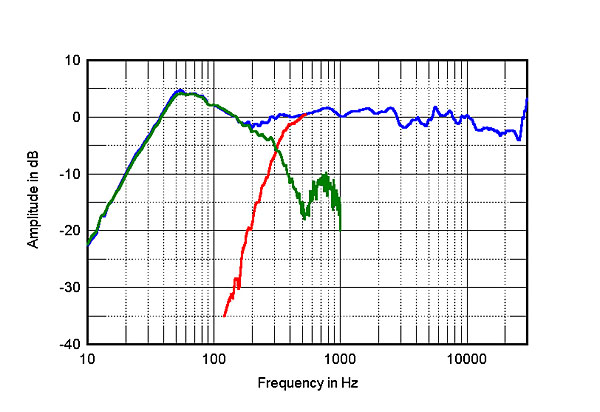
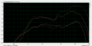
Added to the box geometry, not all drivers, even of the same size, have same dispersion and illuminate it the same way. Here is how an Audax tweeter measures on axis vs 30º in the same cabinet compared to the Morel.
What sofware will simulate this accurately?🙄
Added to the box geometry, not all drivers, even of the same size, have same dispersion and illuminate it the same way. Here is how an Audax tweeter measures on axis vs 30º in the same cabinet compared to the Morel.
What sofware will simulate this accurately?🙄
Attachments
Last edited:
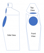
I came up with sketch for my next three way. I previously made a pair of monitor that I called Cleopatra. I'll call this The Sphinx so to give Cleopatra something to ride on.
For now it will be 8 + 5 + 1. I will probably add a 10 later on.
The speakers will have three separate modules. The bass front baffle has similar chamfer as the Avalon Acoustic but the bottom half of the bass will also be angled inward to hopefully will direct any reflected sound away from the listener. Hopefully it will work.
The mid will be in a separate module so that I can try out different shape. Initially it will have a taper on the back end and the front will be chamfered like that of the Avalon.
The tweeter will also be in a separate module. It will probably look similar to the mid but with smaller footprint.
Overall they will look similar to the Avalon but with three distinct differences:
1. Separate module
2. Taper at the back of the mid and tweeter modules.
3. The bass front baffle bottom half is angled inward to minimize reflection.
Attachments
Last edited:
I don't really like to plug our products here, but since you're asking about designs that take into account diffraction, I'd like to share my experience from designing the Dutch & Dutch 8c.
The most important design criteria for the 8c are flat and smooth response, even dispersion and no smearing in the time-domain. All of those dictate you take care of edge diffraction!
Above approximately 3 khz the waveguide on the dome tweeter basically prevents edge diffraction from happening. The waveguide simply makes sure hardly any sound ever reaches the baffle's edges.
Like others said before, edge diffraction can only to some extent be prevented. Where it can't be prevented, what you can do is make sure it is smeared in time and thus frequency. The diffraction will still happen, but in a more controlled and gradual manner, so that it won't lead to significant aberrations at any specific frequency or angle.
In order to effectively smear edge diffraction in time in the range below about 3 khz, I did two things. The first is finding the right baffle dimensions and the best location for the waveguide-tweeter combo on it. Thank god for CNC routers and 3D printers! The second thing I did, was putting a large radius on the baffle edges. To become effective, round-overs generally need to be a bit larger than most people assume! On the 8c I finally settled for a 40 mm radius.
If I had gone for even larger round-overs, diffraction effects in the range between 2k and 3k would have improved marginally, but directivity in the range between 1k and 2k would have been lower, which would have meant a less than perfect directivity match with the cardioid midrange. That's because in this range the secondary sources created by edge diffraction on average actually help to increase the on-axis amplitude. Off-axis this free gain diminishes, so the net result is increased directivity. I thought that was quite interesting.
The round-over of 40 mm for this design was the optimum in terms of response smoothness and directivity control.
If you'd like to have more technical data including measurements, take a look here: http://dutchdutch.com/assets/images/8c-spec-sheet.pdf
- Home
- Loudspeakers
- Multi-Way
- What are some good example of baffle design to improve diffraction