I don't know about this one. In this configuration R4 seems to be making a large change in distortion.
Don't trust blindly to Spice engine.
It's easy enough to try it for real when you build the headamp (it's just one resistor) - you'll hear the difference between 3mA and 10mA of BF862's Id.
Thanks juma, once it's finalized, I'll try it. As you say, it's just a small change. And no, I don't take the simulator results literally.
What gives?
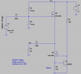
To get an idea of how this buffer behaves, I've implemented it as shown in the attachment. As expected there is definitely a difference in the simulated distortion and that of the real thing.
The setup was 500mA idle current, 1kHz with 616mV RMS amplitude sine wave at the input, dummy 47R resistor as load.
Have a look at the second attachment, the simulated distortion results. Not bad, 5e-05 second harmonic distortion, and 4.4e-07 third. This would amount to about
* fundamental 8.7dBm, or 616mV RMS
* second harmonic distortion -86dB, or 30.8uV RMS
* third harmonic distortion -127dB, or 0.27uV RMS
The question is, how far would the real circuit be from simulation?
Measured the output with both the sound card (using ARTA), and my HP 3585A spectrum analyzer, the results being in agreement, but will just mention the numbers I got out of the spectrum analyzer:
* fundamental 8.7dBm, or 616mV RMS
* second harmonic distortion -51.1dBm, or 716uV RMS
* third harmonic distortion -82.7 dBm, or 15.5uV RMS
It's expected that simulation is different from reality, but why is the difference so large?
Whatever the answer is, how about an experiment regarding the audibility of such distortion. Hooked the output up to a pair of headphones and fed the buffer with a sine wave such that the output was around 716uV RMS. I could hear the tone, not loud, but I could hear it; so 2nd order distortion in these conditions are definitely audible by me. However, lowering the signal to around 100uV RMS I could not hear a thing. And this in the absence of some other loud tone; complete silence, meaning that in these conditions I would not be able to detect any 3rd order distortion.
Edit: forgot to mention the two sine wave experiment; frequencies of 13kHz and 14kHz, same amplitude 512mV RMS. The peak at 1kHz was 39.8uV, which is about -82.1dB.
Attachments


Diamond buffer is quite simple especially if you use FETs as the current sources. Works very well for me.
Hi,
what is the base current of the Follower (Q2) in sim and real life?
I suspect it is ~ double the current passing through R6, i.e. sk170 current is split roughly 1/3 through R3 and 2/3 into Follower base.
Could variation in Follower base current requirement affect the real life performance?
what is the base current of the Follower (Q2) in sim and real life?
I suspect it is ~ double the current passing through R6, i.e. sk170 current is split roughly 1/3 through R3 and 2/3 into Follower base.
Could variation in Follower base current requirement affect the real life performance?
Hi Andrew, I thought so too. Varying the value of R6 does change the distortion in the 2nd harmonic. Lower value for R6 results in lower distortion. The lowest I could get on this prototype was about -63dB distortion in the second harmonic, and about 90dB in the 3rd. One thing I've tried is replacing R6 with a jfet CS. That lowered the distortion a little bit. At this point it's not clear to me how this buffer can be improved significantly and still be kept simple. Perhaps I can live with -60dB distortion in the 2nd harmonic. The buffer was intended as the output in a headphone amp using a direct heated tube in the first stage, so I might just try it out as is.
@jaycee I've considered the diamond buffer but I'm not convinced that it would fare any better than this one.
@jaycee I've considered the diamond buffer but I'm not convinced that it would fare any better than this one.
I'm just guessing, but I think it is that 2/3 : 1/3 ratio of base current:R6 current that is mostly the cause of the increased distortion.
Can you kid on the sim by changing the hFE of the output device to see what effect this base current has on distortion?
Maybe you simply need more current gain between the jFET and the Output.
Can you kid on the sim by changing the hFE of the output device to see what effect this base current has on distortion?
Maybe you simply need more current gain between the jFET and the Output.
Can you kid on the sim by changing the hFE of the output device to see what effect this base current has on distortion?
Maybe you simply need more current gain between the jFET and the Output.
Decreasing the BF parameter from 211 to 111 in the model of 2SC3421, does indeed increase the simulated 2nd and 3rd distortion, but by very little, nothing close to the values I get in the real circuit; e.g. for 2nd, with the small beta the 2nd harmonic distortion is about -80dB, whereas in the real world is about -60dB.
Not that I trusted very much simulated distortion results before, but this makes me trust them even less. It's still interesting that the distortion profiles (simulated and real) do look very similar, i.e. larger 2nd, very small 3rd, and 4th, 5th and the rest are as low as the noise.
Back to the basics; my ramblings might be helpful to other beginners like me, looking for a simple buffer. Replaced the power npns with n-channel mosfets (one can use other mosfets, like irf510, etc.; I used these because I have a whole bag of them). Removed the jfets. Implemented the circuit as shown in the first image. The results are surprisingly close to simulation.
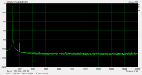
The second image shows the distortion profile for a 1kHz sine wave, 2V p-p input, into a 50R resistor dummy load. This is not a simulation, this is the results from the real circuit. There are some artifacts of the sound card, like the blip at 5kHz and above. What's important for me is just what happens at 1kHz, 2kHz and 3kHz. So, for an input signal of 0.707mV RMS, the second harmonic distortion was at about 59uV RMS, and the third was at about 7uV RMS. This is good enough for me, since I've tested and I can't hear a signal that is anywhere near 100uV.
Sure, if the buffer is to be used with a tube in the previous stage this distortion will be added to the distortion profile of the tube. That would be my next experiment.
Attachments
Are you going to stick with the big output cap or try a DC servo? I've been using Gootee's model with various discrete headphone buffers, and it is shocking to find that the DC servo is typically only -30dB down up into the midrange. Kind of defeats the purpose of a discreet feedback free buffer.
Here is the link for the test setup post #66: http://www.diyaudio.com/forums/chip-amps/107246-dc-servo-question-7.html
You'll want to run this simulation if you decide on the DC servo.
Also with headphone amps I have heard huge improvements going from electrolytic outputs to giant oil cans, so it tells me the electrolytic is nasty on the output.
This along with the difficulty of implementing a DC servo that stays out of the signal path has me moving away from hybrids, I'm starting to think an OPT is the way to go for headphones.
a DC servo with filtering that is only -30dB in the (audio) midband sounds like a badly designed DC servo.
a DC servo with filtering that is only -30dB in the (audio) midband sounds like a badly designed DC servo.
With headphone buffers its not as easy as you think. Two polls at 1hz and you still can have -30db opamp in the signal path because so much output is required of the servo.
The perfect Dc coupled headphone buffer is far from developed, and it is not comparable to preamp buffers. Folks think a headphone buffer would be easy but they are not.
Are you going to stick with the big output cap or try a DC servo? I've been using Gootee's model with various discrete headphone buffers, and it is shocking to find that the DC servo is typically only -30dB down up into the midrange. Kind of defeats the purpose of a discreet feedback free buffer.
Here is the link for the test setup post #66: http://www.diyaudio.com/forums/chip-amps/107246-dc-servo-question-7.html
You'll want to run this simulation if you decide on the DC servo.
Also with headphone amps I have heard huge improvements going from electrolytic outputs to giant oil cans, so it tells me the electrolytic is nasty on the output.
This along with the difficulty of implementing a DC servo that stays out of the signal path has me moving away from hybrids, I'm starting to think an OPT is the way to go for headphones.
Thanks for the link! I should say that I have my own doubts about both the output cap, and dc servo. But will try it, so that I make an informed decision.
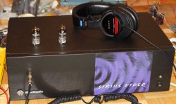
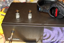
I've been all over the place in the last few months, exploring the headphone amp space. Just finished a very simple tube amp, using one russian 6S45P-E tube per channel (see attached). Can't get simpler than this, the tube being biased with two 1N4148 diodes, output transformer, shunt regulated 150V on the plate. I've tried the same with an autoformer as well, but came back to the transformer. It sounds very nice, no lack of bass and detail, but I'm pressing on, and tested the tube+fet buffer prototype last night. The advantage of this one is that the same buffer can be used with various tubes, even a type 26. My test last night was with a 1S4 triode connected, at 27V on the plate. The measured distortion spectrum was very close if not better than the 6s45pe+opt. But I only built one channel so I couldn't listen to it. Indeed, the disadvantage is the output cap/dc servo. If all goes well I'll be testing both and let you know guys.
Attachments
If all goes well I'll be testing both and let you know guys.
Please do keep us posted. You will also discover that you need a tightly series regulated B+ or possibly a gyrator load to maintain constant voltage at the plate as difting mains are common place (sub .5hz) that go right thru the coupling cap and reck havoc on DC servos.
I've always felt the flexibility of a tube + SS buffer opens incredible possibilities, but we're all just a bit away from pulling it off. My gut tells me that a diamound buffer with extremly well matched transitors, trimmed, with a DC protection circuit/relay, and no DC servo is the way to go, Probably would require a gyrator tube load to hold constant voltage at the tube to buffer coupling cap. I can send you the spice model I'm working on if you want to PM your email address (I don't want to publisize until I know it works in real life.)
The other very good sounding alternative is the discrete JISBOS JISBOS - overview, no DC servo or output coupling caps, but 100% NFB, it is very transperant and probably the best option right now. You can even get PCB's still I believe from AMB laboratories.
If you are looking for a headphone buffer (discrete), I'd go for a simple diamond topology. These can be designed and built with quite respectable distortion performance and can also be easily configured for full class A to drive a pair of 32 Ohm h/phones (you will needs about 270mA to acheive this on a swing of 6Vpk - although I personally dont thing you need more than about 2Vpk).
Its surprisingly difficult to get really low distortion on a heapdhone amp - you really are into 'power' territory, and this even more so if you want to operate open loop.
Its surprisingly difficult to get really low distortion on a heapdhone amp - you really are into 'power' territory, and this even more so if you want to operate open loop.
What I'm really after is a buffer as transparent as possible, to use a direct heated tube in the stage before, which, if we're to believe what others say, has a particularly nice effect on the sound.
At the moment I have a prototype of the buffer with an 1S4 (triode connected) in the first stage. I had it working on the bench supply. I wanted to give this tube a try because it looks like one could get lowish distortion starting at 30V and up. That would be a plus for some people, having both the tube and the buffer supplied by the same source.
A type 26 is in the works too, but of course, high voltage for this one, and a separate low voltage supply for the buffer.
What complicates all of this somewhat is that the power supply is a lot more complex than the amp per se.
A type 26 is in the works too, but of course, high voltage for this one, and a separate low voltage supply for the buffer.
What complicates all of this somewhat is that the power supply is a lot more complex than the amp per se.
ikoflexer,
if I were you, I would take this project very seriously because you have the chance to accomplish something exceptional. When it comes to directly heated tubes and single-ended topology in general, high quality power supply is essential. I wonder if you are ready for the challenge? A common power supply is a bad idea.
if I were you, I would take this project very seriously because you have the chance to accomplish something exceptional. When it comes to directly heated tubes and single-ended topology in general, high quality power supply is essential. I wonder if you are ready for the challenge? A common power supply is a bad idea.
I don't know about being ready for any challenge, but my plan for the power supply is separate shunt regulation for both B+ and buffer, with low output impedance and low noise; for the filament supply I have a prototype gyrator before the filament and ccs after, similar to what Rod Coleman has done, but a bit different. Not sure though, so I might do something simpler for the filament, depending on the tube used.
- Status
- Not open for further replies.
- Home
- Amplifiers
- Solid State
- What about that buffer?