I've been struggling with a headphone amp and being a n00b I came to the realization that I need a good buffer. Maybe not need, but it'd be nice to have a good buffer. Wishful thinking:
* seeeeeeeeeempuuuuuul
* low distortion into a typical low impedance headphones load
* high input impedance
* no matching of devices (I abhor that; yes, I know, I'm not an engineer)
* decent psrr
* ??? what else ???
I really don't know what else would I want from a unity gain buffer? Please, experienced designers, what say you? What does one want, realistically, from a really good buffer?
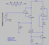
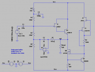
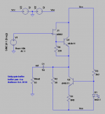
That being said, let's start with something that I'm considering. The attachment shows a very simple buffer. A follower of sorts, a current source there too. I'm sure much better has been done, but it would be nice to have a simple circuit. Have not prototyped this yet, just simulated results.
First attachment, the schematic, which is no surprise; this has been done everywhere, it's not sophisticated.
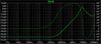
Second attachment, Vcc PSRR.
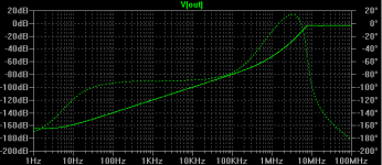
Third attachment, Vee PSRR.
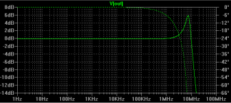
Fourth attachment, frequency response.
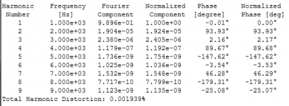
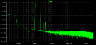
Fifth attachment, distortion number, 1V p-p input, into a 63R load, at 1kHz, 215mA idle current. With higher idle current the distortion becomes lower.
* seeeeeeeeeempuuuuuul
* low distortion into a typical low impedance headphones load
* high input impedance
* no matching of devices (I abhor that; yes, I know, I'm not an engineer)
* decent psrr
* ??? what else ???
I really don't know what else would I want from a unity gain buffer? Please, experienced designers, what say you? What does one want, realistically, from a really good buffer?
That being said, let's start with something that I'm considering. The attachment shows a very simple buffer. A follower of sorts, a current source there too. I'm sure much better has been done, but it would be nice to have a simple circuit. Have not prototyped this yet, just simulated results.
First attachment, the schematic, which is no surprise; this has been done everywhere, it's not sophisticated.
Second attachment, Vcc PSRR.
Third attachment, Vee PSRR.
Fourth attachment, frequency response.
Fifth attachment, distortion number, 1V p-p input, into a 63R load, at 1kHz, 215mA idle current. With higher idle current the distortion becomes lower.
Attachments
You could opt for a Tringlinator:
http://www.diyaudio.com/forums/headphones/165131-tringlinator-mos-based-tringlotron-amplifier.html
The distortion for the complete amplifier is slightly lower at 5x the level and output load halved (32ohm).
The distortion of the tringlotron buffer alone is even lower, and it only requires 4 active elements (6 if the input buffer is included).
I use this one in one of my headphone amps. simple, and it sounds very good:
Audio Buffer in english
Audio Buffer in english
You could opt for a Tringlinator:
http://www.diyaudio.com/forums/headphones/165131-tringlinator-mos-based-tringlotron-amplifier.html
The distortion for the complete amplifier is slightly lower at 5x the level and output load halved (32ohm).
The distortion of the tringlotron buffer alone is even lower, and it only requires 4 active elements (6 if the input buffer is included).
I will look into it, thanks! Do you think that the 3rd order distortion will be lower than the circuit I posted? Also, Elvee, how can you get rid of that nasty output capacitor. For my schematic I can easily implement a servo so there's no need for output capacitor.
@saurus: I would like to not use any opamps (except possibly in a servo).
what headphone, ohms and sensitivity - sensitivity varies orders of magnitude so its an important spec to have for the amp design
if you really don't want to select, trim then jfets really aren't the parts for you - standard grades can have 3:1 parameter spread
having the input jfet bias depend on BJT beta is likely not so good
a b-e resistor is at least approximately constant current
why introduce the mosfet? - another bjt same part # as the output Q would work fine
likewize cascoded jfet ccs bias for the output ccs bias seems a bit overdone if you're not at least cascoding the output Q too
I got the Sony MDR-V6, not exactly audiophile quality, but fine for me. 106dB/mW sensitivity, 63 ohms at 1kHz impedance.
Didn't know an easier way to make it high input impedance and also get rid of high input capacitance.
The mosfet CCS seems to work better then a bjt, as a simple CCS. The jfet ccs can be replaced with a resistor, but the results seem better with the jfets.
Didn't know an easier way to make it high input impedance and also get rid of high input capacitance.
The mosfet CCS seems to work better then a bjt, as a simple CCS. The jfet ccs can be replaced with a resistor, but the results seem better with the jfets.
I don't think so: it will be slightly higher or similar.I will look into it, thanks! Do you think that the 3rd order distortion will be lower than the circuit I posted?
I am afraid it is impossible without inordinate additional complexity.Also, Elvee, how can you get rid of that nasty output capacitor. For my schematic I can easily implement a servo so there's no need for output capacitor.
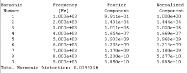
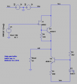
Thank you for your suggestions guys! I tried to change the circuit a bit, and I think I like the change. It's even a bit simpler. 2nd order harmonic distortion has increased a bit, but I don't think I care. 3rd order harmonic distortion has decreased a bit. This is only simulation. Hopefully reality will not be too far from this.
Attachments
output Cap is the "simple" solution
do you actually know just how "nasty" output capacitors are - if their supposed defects could be heard with your system?
basically distortion from Al electrolytics is only measurable on the shoulder of the roll-off - you have to develop some V drop across the C for it to distort
so "super sizing" is one direct approach - make the RC time constant way below audio
further Bateman's "Capacitor Sound" series showed that even this very low frequency distortion is usefully reduced by using "Bi-Polar" Al electros with full thickness oxide on both foils - and using much higher V rating than signal level also helps
I'm fairly certain that a good choice of output Cap will not hurt your sim's distortion #
even an economy/size compromise that allowed 0.01% measureable distortion at 20 Hz and the V drive level that gives 120 dB SPL from you headphones is really unlikely to be audible
you should expect that at 20 Hz thermal effects in your no global feedback amp's semiconductor properties will cause numerically larger distortion that spice doesn't model
No, have no idea how bad my capacitors are or if I can hear them. But it the servo solution is that easy to implement, why not get rid of the output cap?
Well, I just put a prototype together from junk parts, for some sanity checks. Used a J310 as input jfet and 2SD1266A as the bjts. Seems to work just fine, at about 200mA idle current, with a 47R load, no stability issues. My signal generator goes only to a few MHz, but the buffer seems to do just fine up to that range and who knows, even beyond. Didn't run any distortion tests.
Well, I just put a prototype together from junk parts, for some sanity checks. Used a J310 as input jfet and 2SD1266A as the bjts. Seems to work just fine, at about 200mA idle current, with a 47R load, no stability issues. My signal generator goes only to a few MHz, but the buffer seems to do just fine up to that range and who knows, even beyond. Didn't run any distortion tests.
IKO headphone buffer
Hi Iko,
I did a few simulations of your simple HP amp and it's damn good. I've attached the circuit revised for bipolars throughout to make it a bit more resistant to input spikes. Quiescent is about 150mA. Here's the distortion at 10Vpp into 64R:
1 1.000e+03 4.470e+00 1.000e+00 0.00°
2 2.000e+03 2.321e-03 5.194e-04 -98.13°
3 3.000e+03 1.553e-04 3.475e-05 5.68°
4 4.000e+03 2.076e-04 4.645e-05 158.34°
5 5.000e+03 1.662e-04 3.718e-05 -180.36°
6 6.000e+03 1.260e-04 2.819e-05 -179.41°
7 7.000e+03 1.076e-04 2.407e-05 -180.83°
8 8.000e+03 9.469e-05 2.119e-05 -180.89°
9 9.000e+03 8.419e-05 1.884e-05 -180.82°
Total Harmonic Distortion: 0.052599%
This is damn good, as the majority of the distortion is H2, H4 and small amounts of H5 on. The circuit clips at about 9V peak on the negative peak at which point distortion at 1KHz is around 0.231%. I have attached the spectrum plot, which shows perfect stability.
Cheers,
Hugh
Attachments
Last edited:
Hugh, thanks for looking into this. But I have a problem! You threw out the input jfet. My intention all along was to have another stage before the buffer, using one of those very linear direct heated tubes. The overall distortion goes right up if the buffer doesn't have a high input impedance. Your circuit is almost the same as this one, that Dimitri posted in another thread:
http://www.diyaudio.com/forums/headphones/165131-tringlinator-mos-based-tringlotron-amplifier-3.html#post2325334
I have a more general question related to these output stages. How much better can one hope to get by going to a more sophisticated circuit? Specifically, what kind of improvement can can one get regarding the 3rd and higher harmonic distortion numbers?
you could stick 2 op amps together...
how much audio frequency distortion? the word "unmeasureable" springs to mind
Supply Bootstrapping Reduces Distortion In Op-Amp Circuits | New operational amplifiers optimized for high-performance audio and ultrasound applications combine extremely low total harmonic distortion plus noise (THD+N), -130 dB, with large output vo
...
I have a more general question related to these output stages. How much better can one hope to get by going to a more sophisticated circuit? Specifically, what kind of improvement can can one get regarding the 3rd and higher harmonic distortion numbers?
how much audio frequency distortion? the word "unmeasureable" springs to mind
Supply Bootstrapping Reduces Distortion In Op-Amp Circuits | New operational amplifiers optimized for high-performance audio and ultrasound applications combine extremely low total harmonic distortion plus noise (THD+N), -130 dB, with large output vo
Attachments
Last edited:
Since until now it's been just simulation, all I can hope for is that the trend and not the absolute values would be followed in reality. If it looks really bad on paper there's little hope that it will be great in reality. If it looks really good on paper (simulator) maybe one can at least expect non-shabbiness in reality. Plus it's a fun exercise to optimize some spec.
BTW, power supply bootstrapping slightly increased distortion in this buffer above.
BTW, power supply bootstrapping slightly increased distortion in this buffer above.
ps bootstrapping doesn't do much for "no feedback" follower's output Z, gm nonlinearity
you could see an effect with jfet parasitic C nonlinearity and high source Z that would be improved by boostrap/cascode
but using large loop gain to reduce out Z/nonlinearity of an already excellent buffer chip and effectively cascoding the input is what makes Dimitri's composite op amp buffer so good
some ps boostrapping effects aren't properly captured in sim with Boyle style op amp macromodels - transistor level modeling is safest for realistic sim
Last edited:
... If it looks really bad on paper there's little hope that it will be great in reality. ...
And vice versa sometimes. Regardless of what simulating dream machine says, underbiased BF862 (R4 in your sch. in post #10 sets JFET's Id at about 3mA only) will produce thin, unconvincing, grainy/rasp-like sound. With R4=68R (sets Id at about 10mA) and 150-200mA bias through BJTs you'll be enjoying nice, full SE sound.
Also, I routinely use JFET CCS instead of R3 (BF862 with Rs=100R will do nicely).
Last edited:
And vice versa sometimes. Regardless of what simulating dream machine says, underbiased BF862 (R4 in your sch. in post #10 sets JFET's Id at about 3mA only) will produce thin, unconvincing, grainy/rasp-like sound. With R4=68R (sets Id at about 10mA) and 150-200mA bias through BJTs you'll be enjoying nice, full SE sound.
I don't know about this one. In this configuration R4 seems to be making a large change in distortion.
Also, I routinely use JFET CCS instead of R3 (BF862 with Rs=100R will do nicely).
I agree with this one, but will leave it as is for the sake of simplicity.
- Status
- Not open for further replies.
- Home
- Amplifiers
- Solid State
- What about that buffer?