Not sure of the input noise on that one for phono, I also see it is last buy status. There are lots of options for single ended to diff which could then be preceded by a low noise in-amp for diff-in/diff-out.
Thanks Scott. I've done some opamp circuits to go from single ended to differential to feed an ADC. These were used post phono premp with good success. Was just hoping for a nice single chip solution to run differential all the way.
I don't understand how I can use the convolution engine to everything but the DRC (digital room correction).
Can you explain how I can use it to achieve digital RIAA?
It works the same way, RIAA has an impulse response just like your room (I assume reflections are left out of the equation here), you would need to sample the impulse response of an ideal RIAA filter. Someone should be able to help you using LTSPICE.
If someone has a nice RIAA response in a text file, I can convert it to impulse. Or maybe Spice can directly export the impluse? Be sure the impulse is at the sample rate you plan to use. 24 bit word depth would be good.
If someone has a nice RIAA response in a text file, I can convert it to impulse. Or maybe Spice can directly export the impluse? Be sure the impulse is at the sample rate you plan to use. 24 bit word depth would be good.
Come to think of it you might want to window it also, everything always gets more complicated. I have only fiddled with the IIR filter method, easy only 4 numbers to enter and at 192K conformance is absurdly good.
Then it might be better to do IIR filters via plugin. 
There are other things I'd want to filter. A nice high pass for tone arm - cart resonance. A rumble filter. Correction of cart FR and balance.
All easy enough to do in the digital domain.
There are other things I'd want to filter. A nice high pass for tone arm - cart resonance. A rumble filter. Correction of cart FR and balance.
All easy enough to do in the digital domain.
If someone has a nice RIAA response in a text file, I can convert it to impulse. Or maybe Spice can directly export the impluse? Be sure the impulse is at the sample rate you plan to use. 24 bit word depth would be good.
I just built one of these with a 1st order high pass. I can export this file in REW as an impulse wav or text. Is this frequency response acceptable?
Attachments
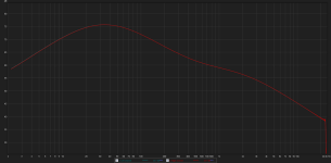
I just built one of these with a 1st order high pass. I can export this file in REW as an impulse wav or text. Is this frequency response acceptable?
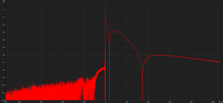
You need the time domain impulse response not the frequency domain for FIR filters.
You need the time domain impulse response not the frequency domain for FIR filters.
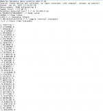
I am too stupid to know what you're talking about. REW lets me export a text of the impulse response. I was showing the freq res so you could decide if it is close enough of a RIAA curve to what you need. This is a screen cap of a small part of it. Is it what you need? I can't post the text file because it is close to 2Mb. PM me your email if you want it.
Attachments
Last edited:
Can't you just move directly to an expression in z by plotting poles and zeros to correspond with the time constants? 'Course you'd have to know Fs.
Can't you just move directly to an expression in z by plotting poles and zeros to correspond with the time constants? 'Course you'd have to know Fs.
This is sort of OK at high Fs but a biquad (or series of biquads) can be made to fit far better. Unfortunately there is no closed form solution but Bob Orban published a numerical technique and a set of solutions years ago. A search will turn up a lot of threads on this on other forums. As I said in the below you might want to tweak the 50.05Hz pole to account for the erroneous use of 50.5Hz in his calculations. The extra zero(s) make a huge difference in making the top end fit out to 20kHz. You can further tweak to add the 50K zero some folks like. You can read the SoX source code to see how these numbers are used. You can also read the miniDSP biquad Excel spread sheet to see how they enter the 48K numbers, the below is the pole/zero representation they use the polynomial form.
44.1 kHz:
SUPPLY # POLES IN Z-PLANE (<=10):2
Zero # Real Imag.
1 -0.2014898 0.000000
2 0.9233820 0.000000
Pole # Real Imag.
1 0.7083149 0.000000
2 0.9924091 0.000000
MAXIMUM ERROR FROM 0.00 Hz TO 20000.00 Hz IS 0.2239207dB
MAXIMUM PHASE ERROR FROM 0.00 Hz TO 20000.00 Hz IS ~+/- 30 degrees
where the "phase error" is computed after a constant delay is added
or subtracted to make the phase error equiripple
SUPPLY # POLES IN Z-PLANE (<=10):3
Zero # Real Imag.
1 -0.5374877 0.000000
2 -0.9884768E-01 0.000000
3 0.9307718 0.000000
Pole # Real Imag.
1 -0.4600918 0.000000
2 0.7371564 0.000000
3 0.9928704 0.000000
MAXIMUM ERROR FROM 0.00 Hz TO 20000.00 Hz IS 0.0113530dB
MAXIMUM PHASE ERROR FROM 0.00 Hz TO 20000.00 Hz IS ~+/- 23 degrees
SUPPLY # POLES IN Z-PLANE (<=10):4
Zero # Real Imag.
1 -0.6929308 0.000000
2 -0.3386390 0.000000
3 -0.5961402E-01 0.000000
4 0.9311520 0.000000
Pole # Real Imag.
1 -0.6658348 0.000000
2 -0.2488928 0.000000
3 0.7389606 0.000000
4 0.9928295 0.000000
MAXIMUM ERROR FROM 0.00 Hz TO 20000.00 Hz IS 0.0005780dB
MAXIMUM PHASE ERROR FROM 0.00 Hz TO 20000.00 Hz IS ~+/- 21 degrees
48 kHz:
SUPPLY # POLES IN Z-PLANE (<=10):2
Zero # Real Imag.
1 -0.1766069 0.000000
2 0.9321590 0.000000
Pole # Real Imag.
1 0.7396325 0.000000
2 0.9931330 0.000000
MAXIMUM ERROR FROM 0.00 Hz TO 20000.00 Hz IS 0.1395898dB
MAXIMUM PHASE ERROR FROM 0.00 Hz TO 20000.00 Hz IS ~+/- 24 degrees
SUPPLY # POLES IN Z-PLANE (<=10):3
Zero # Real Imag.
1 -0.4646165 0.000000
2 -0.8130194E-01 0.000000
3 0.9364602 0.000000
Pole # Real Imag.
1 -0.3741387 0.000000
2 0.7568389 0.000000
3 0.9934040 0.000000
MAXIMUM ERROR FROM 0.00 Hz TO 20000.00 Hz IS 0.0037544dB
MAXIMUM PHASE ERROR FROM 0.00 Hz TO 20000.00 Hz IS ~+/- 16 degrees
SUPPLY # POLES IN Z-PLANE (<=10):4
Zero # Real Imag.
1 -0.6147195 0.000000
2 -0.2762502 0.000000
3 -0.4728733E-01 0.000000
4 0.9365811 0.000000
Pole # Real Imag.
1 -0.5753610 0.000000
2 -0.1881046 0.000000
3 0.7574483 0.000000
4 0.9934112 0.000000
MAXIMUM ERROR FROM 0.00 Hz TO 20000.00 Hz IS 0.0000998dB
MAXIMUM PHASE ERROR FROM 0.00 Hz TO 20000.00 Hz IS ~+/- 15 degrees
88.2 kHz
SUPPLY # POLES IN Z-PLANE (<=10):2
Zero # Real Imag.
1 -0.1168735 0.000000
2 0.9648312 0.000000
Pole # Real Imag.
1 0.8590646 0.000000
2 0.9964002 0.000000
MAXIMUM ERROR FROM 0.00 Hz TO 20000.00 Hz IS 0.0081862dB
MAXIMUM PHASE ERROR FROM 0.00 Hz TO 20000.00 Hz IS ~+/- 3 degrees
SUPPLY # POLES IN Z-PLANE (<=10):3
Zero # Real Imag.
1 -0.3159579 0.000000
2 -0.4655857E-01 0.000000
3 0.9649734 0.000000
Pole # Real Imag.
1 -0.2060289 0.000000
2 0.8597030 0.000000
3 0.9964089 0.000000
MAXIMUM ERROR FROM 0.00 Hz TO 20000.00 Hz IS 0.0000096dB
MAXIMUM PHASE ERROR FROM 0.00 Hz TO 20000.00 Hz IS ~+/- 2 degrees
96 kHz:
SUPPLY # POLES IN Z-PLANE (<=10):2
Zero # Real Imag.
1 -0.1141486 0.000000
2 0.9676817 0.000000
Pole # Real Imag.
1 0.8699137 0.000000
2 0.9966946 0.000000
MAXIMUM ERROR FROM 0.00 Hz TO 20000.00 Hz IS 0.0057028dB
MAXIMUM PHASE ERROR FROM 0.00 Hz TO 20000.00 Hz IS ~+/- 2.4 degrees
SUPPLY # POLES IN Z-PLANE (<=10):3
Zero # Real Imag.
1 -0.3096394 0.000000
2 -0.4513594E-01 0.000000
3 0.9677730 0.000000
Pole # Real Imag.
1 -0.1992839 0.000000
2 0.8703280 0.000000
3 0.9967002 0.000000
MAXIMUM ERROR FROM 0.00 Hz TO 20000.00 Hz IS 0.0000046dB
MAXIMUM PHASE ERROR FROM 0.00 Hz TO 20000.00 Hz IS ~+/- 1.6 degrees
It works the same way, RIAA has an impulse response just like your room (I assume reflections are left out of the equation here), you would need to sample the impulse response of an ideal RIAA filter. Someone should be able to help you using LTSPICE.
Ok, I know the theory of convolution and z-transform, IIR, FIR, etc.
But what about a practical example (using jRiver)?
Any straight link?
44.1 kHz:
SUPPLY # POLES IN Z-PLANE (<=10):2
Zero # Real Imag.
1 -0.2014898 0.000000
2 0.9233820 0.000000
Pole # Real Imag.
1 0.7083149 0.000000
2 0.9924091 0.000000
MAXIMUM ERROR FROM 0.00 Hz TO 20000.00 Hz IS 0.2239207dB
MAXIMUM PHASE ERROR FROM 0.00 Hz TO 20000.00 Hz IS ~+/- 30 degrees
where the "phase error" is computed after a constant delay is added
or subtracted to make the phase error equiripple
SUPPLY # POLES IN Z-PLANE (<=10):3
Zero # Real Imag.
1 -0.5374877 0.000000
2 -0.9884768E-01 0.000000
3 0.9307718 0.000000
Pole # Real Imag.
1 -0.4600918 0.000000
2 0.7371564 0.000000
3 0.9928704 0.000000
MAXIMUM ERROR FROM 0.00 Hz TO 20000.00 Hz IS 0.0113530dB
MAXIMUM PHASE ERROR FROM 0.00 Hz TO 20000.00 Hz IS ~+/- 23 degrees
SUPPLY # POLES IN Z-PLANE (<=10):4
Zero # Real Imag.
1 -0.6929308 0.000000
2 -0.3386390 0.000000
3 -0.5961402E-01 0.000000
4 0.9311520 0.000000
Pole # Real Imag.
1 -0.6658348 0.000000
2 -0.2488928 0.000000
3 0.7389606 0.000000
4 0.9928295 0.000000
MAXIMUM ERROR FROM 0.00 Hz TO 20000.00 Hz IS 0.0005780dB
MAXIMUM PHASE ERROR FROM 0.00 Hz TO 20000.00 Hz IS ~+/- 21 degrees
48 kHz:
SUPPLY # POLES IN Z-PLANE (<=10):2
Zero # Real Imag.
1 -0.1766069 0.000000
2 0.9321590 0.000000
Pole # Real Imag.
1 0.7396325 0.000000
2 0.9931330 0.000000
MAXIMUM ERROR FROM 0.00 Hz TO 20000.00 Hz IS 0.1395898dB
MAXIMUM PHASE ERROR FROM 0.00 Hz TO 20000.00 Hz IS ~+/- 24 degrees
SUPPLY # POLES IN Z-PLANE (<=10):3
Zero # Real Imag.
1 -0.4646165 0.000000
2 -0.8130194E-01 0.000000
3 0.9364602 0.000000
Pole # Real Imag.
1 -0.3741387 0.000000
2 0.7568389 0.000000
3 0.9934040 0.000000
MAXIMUM ERROR FROM 0.00 Hz TO 20000.00 Hz IS 0.0037544dB
MAXIMUM PHASE ERROR FROM 0.00 Hz TO 20000.00 Hz IS ~+/- 16 degrees
SUPPLY # POLES IN Z-PLANE (<=10):4
Zero # Real Imag.
1 -0.6147195 0.000000
2 -0.2762502 0.000000
3 -0.4728733E-01 0.000000
4 0.9365811 0.000000
Pole # Real Imag.
1 -0.5753610 0.000000
2 -0.1881046 0.000000
3 0.7574483 0.000000
4 0.9934112 0.000000
MAXIMUM ERROR FROM 0.00 Hz TO 20000.00 Hz IS 0.0000998dB
MAXIMUM PHASE ERROR FROM 0.00 Hz TO 20000.00 Hz IS ~+/- 15 degrees
88.2 kHz
SUPPLY # POLES IN Z-PLANE (<=10):2
Zero # Real Imag.
1 -0.1168735 0.000000
2 0.9648312 0.000000
Pole # Real Imag.
1 0.8590646 0.000000
2 0.9964002 0.000000
MAXIMUM ERROR FROM 0.00 Hz TO 20000.00 Hz IS 0.0081862dB
MAXIMUM PHASE ERROR FROM 0.00 Hz TO 20000.00 Hz IS ~+/- 3 degrees
SUPPLY # POLES IN Z-PLANE (<=10):3
Zero # Real Imag.
1 -0.3159579 0.000000
2 -0.4655857E-01 0.000000
3 0.9649734 0.000000
Pole # Real Imag.
1 -0.2060289 0.000000
2 0.8597030 0.000000
3 0.9964089 0.000000
MAXIMUM ERROR FROM 0.00 Hz TO 20000.00 Hz IS 0.0000096dB
MAXIMUM PHASE ERROR FROM 0.00 Hz TO 20000.00 Hz IS ~+/- 2 degrees
96 kHz:
SUPPLY # POLES IN Z-PLANE (<=10):2
Zero # Real Imag.
1 -0.1141486 0.000000
2 0.9676817 0.000000
Pole # Real Imag.
1 0.8699137 0.000000
2 0.9966946 0.000000
MAXIMUM ERROR FROM 0.00 Hz TO 20000.00 Hz IS 0.0057028dB
MAXIMUM PHASE ERROR FROM 0.00 Hz TO 20000.00 Hz IS ~+/- 2.4 degrees
SUPPLY # POLES IN Z-PLANE (<=10):3
Zero # Real Imag.
1 -0.3096394 0.000000
2 -0.4513594E-01 0.000000
3 0.9677730 0.000000
Pole # Real Imag.
1 -0.1992839 0.000000
2 0.8703280 0.000000
3 0.9967002 0.000000
MAXIMUM ERROR FROM 0.00 Hz TO 20000.00 Hz IS 0.0000046dB
MAXIMUM PHASE ERROR FROM 0.00 Hz TO 20000.00 Hz IS ~+/- 1.6 degrees
tl;dr
I don't know what kind of digestion you've got Scott, evidently it's more robust than mine. Definitely a conversation-stopper. I liked the first para tho'. Thanks.
Ok, I know the theory of convolution and z-transform, IIR, FIR, etc.
But what about a practical example (using jRiver)?
Any straight link?
I will post some impulse files later today for you to try.
Ok, I know the theory of convolution and z-transform, IIR, FIR, etc.
But what about a practical example (using jRiver)?
Any straight link?
This is a link to a free VST plug-in that as far as I can tell you simply drop into jRiver's plug-in folder.
I know nothing about jRiver or VST but the process seems simple enough just like Photoshop effects.
(( vacuumsound ))
Nobody wants digital RIAA. It's totally at odds with a preference for vinyl.
Ah, I must be nobody...
There's always one.
Vinyl freaks will reject this in their hordes. It stands to unreason.
Seriously, do you see many unplugging their passive RIAA from their lovingly-assembled end-to-end-analog systems to make room for one digital component?
Vinyl freaks will reject this in their hordes. It stands to unreason.
Seriously, do you see many unplugging their passive RIAA from their lovingly-assembled end-to-end-analog systems to make room for one digital component?
Last edited:
I really don't care what vinyl freaks want. I want as little analog signal processing in my system as possible. I enjoy playing LPs now and then. I also have a Victrola, which is pleasant in its own way.
Seriously, do you see many unplugging their passive RIAA from their lovingly-assembled end-to-end-analog systems to make room for one digital component?
Wrong audience, if you check a wider range of forums you will find lots of folks doing this. Nothing but old farts here.
Seriously, do you see many unplugging their passive RIAA from their lovingly-assembled end-to-end-analog systems to make room for one digital component?
Dunno about "many," but I'd sure do it.
- Home
- Source & Line
- Digital Line Level
- What about digital RIAA?