Hi Guys
Long time not much to post for me, too much side effects because of that pandemic situation..
Now my Question to all of you is:
What do you think about a CLASS A AMP which runs almost cold if its run below 5 Watts. 25degree Celsius max
This for days or weeks because it will take only 0.35AMP IDLE Current
No need for Fans, can handle Loads as low as 2 Ohms and has a bandwidth 10 - 100Khz +- 1db
Runs on Dual Rails +- 35 Volts is NON Mosfet
Distortion is about 0.03 % under 5 Watts and will claim to 0.4% @ Full load 2 - 8 Ohm doesn't matter
Output max @ 8 Ohms is 15Volts RMS 28 Watts
Sound is good to excellent.
More there is no need for large Toroid Transformers
All my speaker ar 4Ohms and the Amp doesn't heat up.
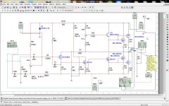
Will Post Schematic later, so you guys can use your Spice Programs to test.
Now, I have built it, and testing the latest Prototype with the oldest one.
But just to make one thing clear if pulled up to full load it will get hot but again no one is listening all day at 25 or more watts all day.
This is the outcome of the discussion we had once about wasting Power with Class Amps and melting the Ice away from Polar Zones.
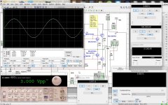
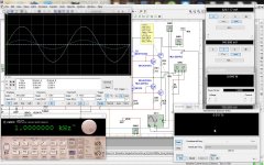
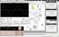
Check out the pics, left is Prototype 1 which I made 18months ago, right is Prototype 9 which I made past September, soon number 10 the final one will follow.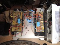
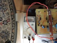
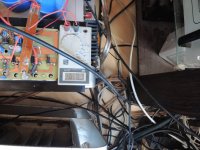
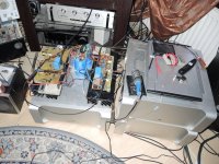


I'm sure it sounds great, but are you sure about your numbers?
0.35A bias allows at max 0.25Arms output current, into 8 ohms that's about 0.5W.
Just 125mW into 2 ohms.
Anything above that is outside class A.
Jan
0.35A bias allows at max 0.25Arms output current, into 8 ohms that's about 0.5W.
Just 125mW into 2 ohms.
Anything above that is outside class A.
Jan
@jan.didden
the reason to built this is, that it makes not much sense to burn away hundreds of watts just to listen to regular Room level with Class A. I can sing a song of this. The Single End Class A I build in 2020 uses 750 Watts in Standby @ Line Voltage 230.Volts.. So imagine.
Also above I wrote IDLE Current, with this I meant while in Standby .
I modified my earlier built CLASS A Single End, where I used a 400 Watt 8 Ohm Resistor to make that Common Current Source , which is Single Ended, to a Variable Current Source where Idle is set by R13 & VR2 to 0.35 AMPS this will allow to have that Amp working in Pure CLASS A Mode even with a 2 Ohm load. The upper Limit is set with VR2 only.
Now to gain more Output Power I use a very easy way to achieve Power up to 100 Watts @ 2Ohms which is 15 volts RMS into 2 Ohms..
Of course now BIAS has to increase by itself and this can be done if we Set Idle Current to the Signal Transistor of the Amplifier
The Transistor which comes in for the Common Current Source Resistor from Earlier Builds we can adjust so that it will work when Power increases as signal increases. End State we will have @ a 2 OHM about 4 Amps Current (Measured) understood @ 15.Volts RMS output 15x15=225 : @ 112.5 Watts RMS but this the amp can't do, because the VRAIL + and VRAIL - will drop * The Transformer I use delivers max 5 Ampere @ 35 volts DC.
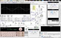
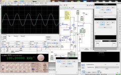
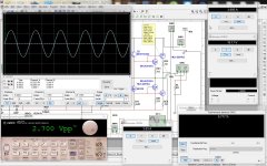
Please check the Circuit, also the Screenshots I added. And No for anyone else who are suspecting a A/B Amp, no it's all the way Pure Class A. The only difference from other Class A it will not heat up as long as we do not drive the Amp into more than 10 Watts and even then it's still in normal matter where heat seldom crosses 40 Degrees Celsius.
8 pieces MJL4281 are used as Outputs.
It draws while no signal is applied, only 20 Watts from LINE POWER @ 220Volts..
And under normal listening condition not more than 30 Watts.
PCB is made here at home, double sided through whole. I bought the tools set to make this happen.
This is just a modified Version of a circuit which actually was drawn long time ago by Elliot sound, but it's very different in many parts of it, but still also has some similarities, so all the credit for the Idea goes to Elliot sound. Even the Elliot Sound Circuit uses Single Rail. BTW the measurements I also get even better on the already built amps compare to simulation.
Thanks for Reading
Chris Hess


 .
.
the reason to built this is, that it makes not much sense to burn away hundreds of watts just to listen to regular Room level with Class A. I can sing a song of this. The Single End Class A I build in 2020 uses 750 Watts in Standby @ Line Voltage 230.Volts.. So imagine.
Also above I wrote IDLE Current, with this I meant while in Standby .
I modified my earlier built CLASS A Single End, where I used a 400 Watt 8 Ohm Resistor to make that Common Current Source , which is Single Ended, to a Variable Current Source where Idle is set by R13 & VR2 to 0.35 AMPS this will allow to have that Amp working in Pure CLASS A Mode even with a 2 Ohm load. The upper Limit is set with VR2 only.
Now to gain more Output Power I use a very easy way to achieve Power up to 100 Watts @ 2Ohms which is 15 volts RMS into 2 Ohms..
Of course now BIAS has to increase by itself and this can be done if we Set Idle Current to the Signal Transistor of the Amplifier
The Transistor which comes in for the Common Current Source Resistor from Earlier Builds we can adjust so that it will work when Power increases as signal increases. End State we will have @ a 2 OHM about 4 Amps Current (Measured) understood @ 15.Volts RMS output 15x15=225 : @ 112.5 Watts RMS but this the amp can't do, because the VRAIL + and VRAIL - will drop * The Transformer I use delivers max 5 Ampere @ 35 volts DC.
Please check the Circuit, also the Screenshots I added. And No for anyone else who are suspecting a A/B Amp, no it's all the way Pure Class A. The only difference from other Class A it will not heat up as long as we do not drive the Amp into more than 10 Watts and even then it's still in normal matter where heat seldom crosses 40 Degrees Celsius.
8 pieces MJL4281 are used as Outputs.
It draws while no signal is applied, only 20 Watts from LINE POWER @ 220Volts..
And under normal listening condition not more than 30 Watts.
PCB is made here at home, double sided through whole. I bought the tools set to make this happen.
This is just a modified Version of a circuit which actually was drawn long time ago by Elliot sound, but it's very different in many parts of it, but still also has some similarities, so all the credit for the Idea goes to Elliot sound. Even the Elliot Sound Circuit uses Single Rail. BTW the measurements I also get even better on the already built amps compare to simulation.
Thanks for Reading
Chris Hess


 .
.Member
Joined 2009
Paid Member
Yes.
My goal was to build and amp which uses only as much Power as needed, but also with Class A sound and feeling.
If we remove Resistor 13 or changing the resistance to 10 Ohms or more then the Amp will be in common current source and will use up Power, just to change it to heat.
that way, the amp decides how much power it needs to work at any output level. when used just at Room level, then we have a CLASS A AMP which also brings the CLASS A SOUND, the linearity the punch the sweetness and also finesse of a good Amplifier. But with almost no heat.
Even running this amp for a week or more without switching off, it won't get hot.
The Amp underneath we can see in the picture, this one will reach 85 degrees when the Fans are on. and this temp it reaches within 10 minutes after applying power. Even the Fans will kick in at 75Degrees Celsius. After that it will run at the temp of 85 Degrees and Fan speed will variate increase when the Amp gets hotter or lower the speed of the Fans when the amp gets colder.
The new one does not need any fan.
I will post Realtime measurement soon.
The definition of class A is that both output halves are conducting throughout the full signal cycle.
That means that the bias current must be set to allow the highest expected output current.
If you tell us the bias current you are using, we know the class A output level.
Your previous mention of 0.35A bias only allows 0.5W in 8 ohms in class A; higher output levels will then be in class AB.
Maybe you have developed something like sliding bias, if so please explain how you did it. Dozens of screenshots do not explain it.
Jan
I think I have already explained it in my last post.
R13 is locking TR7 & 8 almost to VRail -
If we remove R13 then full current flows - or as much as is adjusted with VR2 usually about 4 amps for this 100 Watts @2 Ohms.
Using R13 eliminates some of this unused current, at least this is what I think that it happens, but I can set the current higher or even lower. Lower is not a good option because it decreases sound Quality.
Note that Q3 is a 50 Watts Transistor which has only the function of sending enough current to the output transistors. there was a lot of testing involved lot of transistors went to transistor heaven. even after simulating with my spice program. Rows of BD 139 ended up death just while powering up the amp. talking about Q3.
I can remove Q3, and the amp will still run. but not lots of power increasing R13 to say 5 ohms then it might get 1 Watt but inserting Q3 with the same 5 Ohm Resistor R13 then the amp will deliver Full Power and draw at least 3 - 5 Ampere depends how VR2 is adjusted.
I once had to repair a prototype and there I found out that this plays a big role on the Current consumption of this amp. So that was a long way and I actually got what I wanted.
But I'm happy to shoot a Video for you just to see that this amp really increases Current when Singal increases.
There were many other problems which made me spend a long time of testing otherwise I would not need to make to 9 PCB's
Don't forget I'm just someone who tries to build a good Amp.
Anyway I read alot here. and I'm happy to welcome any input of you guys ..
Thanks
Have you taken a look at the Circuit; I think that is self-explaining.
It began a long time ago to build Amplifier even my qualifications aren't in that way but started out as a hobby in the 70'ies.
and it never ended. But Amps got better and better and so on. Finally, then Computer made everything a lot easier, and all these Simulation programs
one can try many things and some kind of general electronic understandings makes everything a lot easier.
But the most important things are patience even if some smoke appears at switch on. and some logical thinking what can be done and what not.
And then I got help from some people who know what all is about. And I listen to them very carefully.
Again, my goal was to have a Class A which uses only that much Current as there is need of.
BTW I always thought that AB is half wave signals split at the input and then put together at the output sometime even inverted phase. This amp does no where split the signal at least I couldn't find it. So now I can listen to my Music without heating up my living room.
This Amp here, if I remove Transistors 5&6 then I still have sound, If I remove Transistor 7&8 instead then I do have no sound anymore. Because 5&6 are Current transistors. and 7&8are Signal transistors and then this amp is Single End Class A I think. Please correct me if I'm wrong I'm willing to learn
Thank you guys
I will be back with a Video
Chris Hess
Look at the waveforms across RE1-4. You will see when the output transistors cut-off.
As you found out, the bias current through Q3 and Q4 is poorly controlled.
Ed
As you found out, the bias current through Q3 and Q4 is poorly controlled.
Ed
Amplifier class is not about the sound nor feeling. Class A in audio amplifier is simply defined as stated by Jan Didden.... My goal was to build and amp which uses only as much Power as needed, but also with Class A sound and feeling....
Your amp splits the signal at Q4.... BTW I always thought that AB is half wave signals split at the input and then put together at the output sometime even inverted phase. This amp does no where split the signal at least I couldn't find it....
Which circuit are you discussing? VCSCAA?
How is the sliding bias working, through R7?
Let us focus on that, do not distract with irrelevant blather.
Jan
How is the sliding bias working, through R7?
Let us focus on that, do not distract with irrelevant blather.
Jan
If it's a push-pull amplifier, one output device current will go to 0.7 A and the other to 0 A at the end of the class-A region, so the peak output current is 0.7 A, the RMS current when playing a sine wave almost 0.5 A and the class-A sine wave power almost 2 W into 8 ohm.I'm sure it sounds great, but are you sure about your numbers?
0.35A bias allows at max 0.25Arms output current, into 8 ohms that's about 0.5W.
Just 125mW into 2 ohms.
Anything above that is outside class A.
Jan
Yes correct.
Still the question on this amp, how it works, stands.
I am genuinely interested.
Jan
Still the question on this amp, how it works, stands.
I am genuinely interested.
Jan
No this is my name for this Amp.. Variable Current Source Class A AmplifierWhich circuit are you discussing? VCSCAA?
How is the sliding bias working, through R7?
Let us focus on that, do not distract with irrelevant blather.
Jan
No, it's no push pullIf it's a push-pull amplifier, one output device current will go to 0.7 A and the other to 0 A at the end of the class-A region, so the peak output current is 0.7 A, the RMS current when playing a sine wave almost 0.5 A and the class-A sine wave power almost 2 W into 8 ohm.
Just uploaded a Video is short but very explainable
This amp is ALWAYS ON Variable Current Source
No split unless you do not know Class A Q4 is just a Impedance ChangerAmplifier class is not about the sound nor feeling. Class A in audio amplifier is simply defined as stated by Jan Didden.
Your amp splits the signal at Q4.
Sorry No split at Q4. Q4 is just the Signal Driver for 7&8 BTW there are 8 output TransistorsAmplifier class is not about the sound nor feeling. Class A in audio amplifier is simply defined as stated by Jan Didden.
Your amp splits the signal at Q4.
- Home
- Design & Build
- Construction Tips
- What about a COLD CLASS A Amplifier