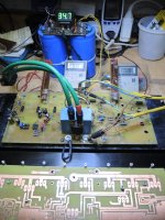
NO, it does not look like that. It's a perfect Sine Wave up to 100Khz at full load as well as any other level.This also might help clarify.
View attachment 1115399
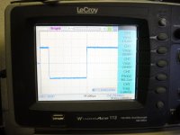
Class "AB" which is when there is an overlap of the two devices as in this image:
View attachment 1115401
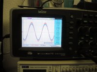
If you scope the emitter resistors, at full power it will look like the bottom waveforms I think.
View attachment 1115400
Besides working as a hobby on Amplifiers I also have a Business to run, which takes a lot of time. So I cannot always reply as I would like it.
BTW I use Le Croy Scope digital 100MHz Dual Channel, with Digital Read out with for me to many functions.

No one says that original JLH or Death Of Zen (derived from JLH) are not class A amplifiers. Your design is simply not operating in the class A. Problem is that you made changes not understanding completely what are consequences. There is no circuit property that would provide sliding bias and initial bias is adequate for AB class only.Never mind the critics, but the guy who designed this is Rod Elliot, and do you really believe a guy of his caliper needs to cheat on a design. Writing that it is Class A when in reality it is Class AB according to you?
Did you measure as required: “across any emitter resistor RE1, RE2, RE3 or RE4 at full power output into 4Ω or 8Ω load”?NO, it does not look like that. It's a perfect Sine Wave up to 100Khz at full load as well as any other level.
Clarification: was oscilloscope ground connected to one RE resistor leg and probe directly to other leg of the same resistor?
I do not criticize your circuit, you showed enough that it works just fine. However I do not agree with your definition of splitter. I also asked you to measure voltage of the emitter resistor which you did not make, probably because you do not know how to do that.... Take a good look and you will find that the circuit of Rod Elliot is very Similar to this one which you criticize here.
Never mind the critics, but the guy who designed this is Rod Elliot, and do you really believe a guy of his caliper needs to cheat on a design. Writing that it is Class A when in reality it is Class AB according to you?...
A circuit does not define an amplifier to be class A or AB. Operating mode of an amplifier defines class A or class AB. On certain cases, the same circuit can be used as class A or AB depending on how a user set the bias of the output device. It is this concept that you lack proper understanding, made worse by ignorance on how to make measurement on operating mode of an amplifier. Please consult relevant reference on basic electronics. It is not possible to discuss technical matters without proper use of nomenclature.
Last edited:
True, it may if amplifier ground is connected to the power earth, which is likely.The advice in the last sentence may call for trouble .. short output.
Better to use both oscilloscope channels and measure difference. Somewhere in Rigiol's manual math operations section, there is how to use two channels subtraction. Probes should be connected to both ends of resistor under measurement and oscilloscope ground to the amplifier ground. That would give signal across two measurement points with no risk of short circuit.
However, we know what measured signal will look like. It will be sine half-waves.
I'm sure it sounds great, but are you sure about your numbers?
0.35A bias allows at max 0.25Arms output current, into 8 ohms that's about 0.5W.
Just 125mW into 2 ohms.
Anything above that is outside class A.
Well, that is only true in some Class A Single ended class A. Class A PUSH PULL amplifiers have the hability to modulate current up to twice the value of quiescent current. So the output of a class A push pull amplifier with 0.35 QUIESCENT CURRENT would allow for 0.7A, at max 0.5Arms output current into 8 ohms thats about 1W.
You are right! 2W , my bad0.5Arms in 8 ohms would be 2W.
(0.5^2)*8
Jan
Hm, catchy title. Im not an expert, but the truth probabbly is somewhere in the middle. Pioneer SA-7800; SA-8800; SA-9800: ''NON-SWITHHING''. I own a SA-7800, no 8800 or 9800 - it was a matter of money.... Sounds superb/SA-7800/! What more? How colder should your class ''A''.
- Home
- Design & Build
- Construction Tips
- What about a COLD CLASS A Amplifier