If you do not wish Q4 to split the signal then do not connect collector of Q4 into bases of Q5 and Q6.
I will answer all the Question in the Coming days and also prove my words. Making a Video with function Gen distortion Meter and all what comes with it.. Also digital Scope with all read out there might is.
@jan This is the Circuit as it is. I also have Artwork double sided. you use whatever you like.
BTW this amp has also a Very Ultra Fast Servo Control which is not drawn in the circuit, but I make it available here. It in fact a PID which controls input and output and does not interfere with the signal in no way, it's just checking for 0 Volts. and with this I mean 0.00001 Volt.
One more thing: This amp also runs on +- 12 volts.
thank you all for your input
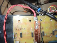
What do I see on the multimeter? Is this representing a current? No idea where it is measured.Guy
I just made a small Video for you to watch.
This Explains it..
Is it the current in an emitter resistor? Of course the average current increases with music but that doesn't mean that the bias current increases.
Can you please, please EXPLAIN what's going on? The video does not explain anything, it just shows something, not sure what.
Just assume I am a friend (difficult, I know ;-) and you EXPLAIN to me how the circuit works, how you set the bias, how does the bias increase with music (if that is what happened). You know, one engineer talking to another over coffee.
Jan
Sorry again, Q3 is Current SOURCE no signal the Output of it just gives current for BD139 Q4 , Q5 & Q6 and if you look then you see that this BD 139 is NPN Sending output is Emitter Signal transistor Q7 & Q8. BTW when I write Split Signal then I mean Split it into +Wave and -Wave and this does not happen here.. It's fully Class A. I can remove Q3 Q5 Q6 and the amp still sounds, but not lots of power max 1 Watt. instead of Q3 Q5 Q6 I can use a 10 Ohm 200Watts Resistor Direct to BD 139 - But then BD 139 will break within seconds. Exchanging it to a MJL4281 it will sound and not break. But frequency response is low max 35KHZ at max.If you do not wish Q4 to split the signal then do not connect collector of Q4 into bases of Q5 and Q6.
I'm working on this one almost 2 years by now.. started December 2020.
Still I appreciate any input. BTW it works like a dream.
Fuse 2.5 amps Rail + 35 Volts from Power Supply is in Serie instead of the Fuse.What do I see on the multimeter? Is this representing a current? No idea where it is measured.
Is it the current in an emitter resistor? Of course the average current increases with music but that doesn't mean that the bias current increases.
Can you please, please EXPLAIN what's going on? The video does not explain anything, it just shows something, not sure what.
Just assume I am a friend (difficult, I know ;-) and you EXPLAIN to me how the circuit works, how you set the bias, how does the bias increase with music (if that is what happened). You know, one engineer talking to another over coffee.
Jan
Attachments

Sorry, but your explanation leaves a lot to be desired. I do not wish to argue, but you need to brush up on your basic electronics. No more comment from me.Sorry again, ...
In the video I try to show increase and decrease of current on the Amplifier when Signal is increased respectively decreased .
Common Current Source Class A will neither increase nor decrease by changing the Signal on the input of the Amplifier. this when hi current is applied will be heat of the transistors. So now here comes what I did, reduce current R13 of Q7 Q8 to Be only increased when Signal is applied. therefor the Amp will not get hot like a stove when not in use. or only on low Volume. and the polar Bears will continue to walk on the ICE The sound is tremendous good.
I accept anyone here, also respected.
Two years ago, we had a discussion on wasting Power on Class A. That day I promised myself to change this, now I'm almost there.
Thanks anyway for your input. I have seen your works and I have great respect.
The last Class A I built runs with 4 Ampere IDLE or Call it BIAS and this with 40+ 40- Rails.. Current Source 8 Ohms 200Watt resistor, had to increase to 400 Watt because the Resistor broke and sometimes showed 125 or more degrees Celsius. Now this Amp here uses almost the same Circuit as the old one except the Current source. Now its manageable and low current while the amp is not used or only on low level.
Chris
Your welcome, thanks for your inputSorry, but your explanation leaves a lot to be desired. I do not wish to argue, but you need to brush up on your basic electronics. No more comment from me.
Yeah you might right, but this is still full wave and not only half wave there is my point of it..
and it's still class a, even if Collector sends out the inverted Signal to Base of q5 q6 but only to give current to Q7 Q8.
But I'm talking about split signal into two half Waves. This is not the case here. if it this what you mean with split the I agree with you if you mean splitting into half wave then Sorry, can't agree because my Scopes tell me something else.
Last edited:
So, you are basically confusing current pulled from rail to be delivered to load as a sliding bias.Fuse 2.5 amps Rail + 35 Volts from Power Supply is in Serie instead of the Fuse.
Don’t you find any problem with fact that there is only 50 mA idle current through pairs of output transistors and 0.3 A through Q3/Q4? That makes for 10 W dissipation at BD139. You mentioned many burned ones.
For me, this is a class A/B amplifier. The only unusual I can see, is the quite high bias in the driver transistors.
What has this to do with class A??Fuse 2.5 amps Rail + 35 Volts from Power Supply is in Serie instead of the Fuse.
The way I see it, with the DC voltage on R13 you set the bias. For 0.35A it should be 0.78V across R13, right?
This is also the driving signal for the output stage. The 0.35A also flows through the top output pair.
So when the signal increases, the output current rises until it goes higher that 2 x 0.35A (thank you marcel) at which point the top pair no longer decreases current and the bottom pair increases current in a half pos sine wave. Since your multimeter is an average responding DC meter, you see more voltage across R13 when your signal output current gets above 0.7A. But the bias current is unchanged; I see no mechanism that changes it.
A similar reasoning can be set up for the top pair.
It is a class AB amp with 0.5Arms output current in class A, anything above that is in class AB.
Now if any of this is wrong, please correct me. No more irrelevant Youtubes please, be serious.
Jan
Jan I think we have a big misunderstanding here.
So I think best thing to do, we do drop this. Makes no sense. Might my understanding of CLASS AB is certainly different from yours.
And in this case I could give you 100 Examples of so called Class A Amplifiers which in Reality are running in CLASS AB but are Biased in CLASS A.
Here this is not the case.
Enjoy your day and it was nice to talk to you.
But your point is very interesting. I need to talk to someone..
Regards
Chris

Please show oscilloscope measurement photo of voltage across any emitter resistor RE1, RE2, RE3 or RE4 at full power output into 4Ω or 8Ω load.Here this is not the case.
This also might help clarify.

Class "AB" which is when there is an overlap of the two devices as in this image:

If you scope the emitter resistors, at full power it will look like the bottom waveforms I think.

Class "AB" which is when there is an overlap of the two devices as in this image:
If you scope the emitter resistors, at full power it will look like the bottom waveforms I think.
Last edited:
Can you find a single one among those 100, that works up to less than 1% of rated power in A class, and is still considered as an A class amplifier?I could give you 100 Examples of so called Class A Amplifiers which in Reality are running in CLASS AB but are Biased in CLASS A.
Your amplifier is working in A class only up to 0.1 W at 8 Ohms. If measured rail current is 0.35 A at idle state, then only 50 - 80 mA goes through output transistors. To pass some current, Q7/Q8 Vbe must be at least 0.6 V. So, there is about 0.61 V across R13 and about 0.28 A through it.
You have AB class amplifier that you are happy with. That’s great. Just don’t call it cold class A. 😉
What is class A or AB amplifier is not open up for voluntary interpretation from hobbyists like me and you.Might my understanding of CLASS AB is certainly different from yours.
Do what is proposed by indra1 and kodabmx and that would give the definitive answer.
I asked the OP to do that back on post #11.Do what is proposed by indra1 and kodabmx and that would give the definitive answer.
Ed
Ah yes, you did. Despite hpro’s claim that “I'm happy to welcome any input of you guys”, several comments or questions were simply ignored. 🙂I asked the OP to do that back on post #11.
Ed
Guys you are all very nice and I'm really thank full for your input.
before you advance more than this, please read here: https://sound-au.com/project36.htm
Take a good look and you will find that the circuit of Rod Elliot is very Similar to this one which you criticize here.
Never mind the critics, but the guy who designed this is Rod Elliot, and do you really believe a guy of his caliper needs to cheat on a design. Writing that it is Class A when in reality it is Class AB according to you?
BTW I mentioned this above already, that I took his Circuit or say his design to modify, so he knows that for a long time. As other guys knowing it too.
My modifications are more cosmetic than anything else, changing from Single Rail to dual rail and changing some of the transistors that these don't break. that fast. The circuit is online, all you need to do is use your spice program and test it the way it was drawn. instead of using 24 Volts using 35 to 40 Double Rail + - Gnd adding also Q2 which is impedance matching transistor. but in big scale it very similar to Rod Elliots Circuit. the main section like input -drive and output are almost 1:1
But it was not him who placed this here, it's me because I modified it and this for quite a long time. So, I'm old enough to take the blame.
Thanks, some definitions with my Spice program will follow, like Split Signal what it really means for me. For me, when a Signal is separated into two Waves, Positive and Negative at the input of the amp and then put together at output stage.
Q4 in this circuit uses the full Signal on both outputs like Collector and also Emitter without cutting off either the lower or the upper part of the Wave and this is not a split. where the Signal at the collector is in Phase and the one on the emitter is 180Degrees out of phase. but still FULL WAVE and not in any kind a split wave.
Idle Current: R 13 is enough current to have the amplifier run to a certain power output.
Now, it is possible to also create some electrical Sensor Switch, which would set the BIAS of the amp to full load if crossed a certain Power level. And then set a second switch that it revokes the Full Bias as soon the Amplifier does not use that much Power, so cut down the BIAS to that level. But this would rather be complicated. I have done that before and it works but not really satisfying.
No Class AB will run and have sound if either upper or lower drive and output transistors are disconnected. This amp will still run, as long Q7 Q8 is in the circuit. I repeat myself I know.
- Home
- Design & Build
- Construction Tips
- What about a COLD CLASS A Amplifier