They have nothing to do with gain and everything to do with oscillation.
Just stick one end of the resistors into the input pads and attach your signal wires to the other end, so the 2.2K are in series with the signal hots. That's what Wayne did on an earlier PCB and it worked perfectly.
Just stick one end of the resistors into the input pads and attach your signal wires to the other end, so the 2.2K are in series with the signal hots. That's what Wayne did on an earlier PCB and it worked perfectly.
I think these are the right part - 531102B02500G Aavid Thermalloy | Mouser
1" pin spacing, and choose height to fit in your enclosure of choice
Thank you for your time and effort in this.
That is what I am looking for.
They have nothing to do with gain and everything to do with oscillation.
Just stick one end of the resistors into the input pads and attach your signal wires to the other end, so the 2.2K are in series with the signal hots. That's what Wayne did on an earlier PCB and it worked perfectly.
Thanks 6L6, i will do that!
Ok follow up question. If i want to add a LED for power indication on frontplate, where would be a good place to tap its power? I am using LED reference for the vregs. Can i use the + lead of R10 or would that mess with the reg?
Alternatively, can i use the small unpopulated solder hole on the PSU side coming from the 7915 and reverse it with respect to gnd?
Alternatively, can i use the small unpopulated solder hole on the PSU side coming from the 7915 and reverse it with respect to gnd?
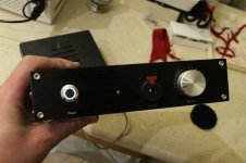
Finished the amp and am spending time with it today. My current impression is that it just sounds natural. I am listening on AKG k712 pros and everything sounds right. I was surprised to find that it drove my DT770 600 ohms to similar levels as these (600 vs 62 ohms), anyone care to explain that? Goes without saying, they also sounded great through this amp (though i can never listen to them for very long as they feel like having my head in a vice).
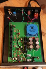
A bit about the build:
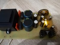
Opamp is 2xOPA627. Board is an earlier rev (without the 2.2k resistors, which i added per 6L6s instructions). I got matched pairs of 2SK2013s and 2SJ313s from liubincalvin. Bias is 60 mA.
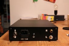
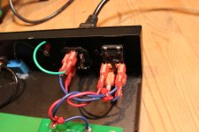
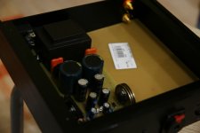
I used a chassis from audiophonics that is slightly larger than the hammond one to get some extra space. This worked nicely (though some cutting and filing was required to make connectors fit), but i had some hum problems in the beginning when touching the pot. I think this was because the anodization of the aluminium meant the backplate was not electrically connected to the rest of the case. So i put a connection between backplace and rest of chassis and filed away the anodization at both points and now the hum is gone.
I ended up running the power indicator LED from the + side of R10 and - side of R14 so that both halves share the load, and used a 3.3kohm resistor to limit the current. I realize i made a glaring mistake in not ordering any blue LEDs... woops!
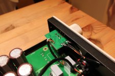
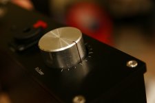
The volume pot runs off a small separate board which makes it a bit easier to fit without mounting the PCB flush with the frontplate. Got a bit tight with the wiring but i think it turned out OK. All internal signal wiring is Canare L-2B2A, which is nice and thin and really easy to work with (and the only microphone wire i had lying around).
The face and backplate are my very early learning experiences from making stencils! I had some trouble getting the stencils to lie flat against the metal, which is why the outlines are bit fuzzy here and there, but hey, this is DIY (and stencils is hard!) 🙂
Thanks Wayne for a great design, and 6L6 for another well-illustrated and easy to follow guide. This was a lot of fun, and i am enjoying this amp a lot!
A bit about the build:
Opamp is 2xOPA627. Board is an earlier rev (without the 2.2k resistors, which i added per 6L6s instructions). I got matched pairs of 2SK2013s and 2SJ313s from liubincalvin. Bias is 60 mA.
I used a chassis from audiophonics that is slightly larger than the hammond one to get some extra space. This worked nicely (though some cutting and filing was required to make connectors fit), but i had some hum problems in the beginning when touching the pot. I think this was because the anodization of the aluminium meant the backplate was not electrically connected to the rest of the case. So i put a connection between backplace and rest of chassis and filed away the anodization at both points and now the hum is gone.
I ended up running the power indicator LED from the + side of R10 and - side of R14 so that both halves share the load, and used a 3.3kohm resistor to limit the current. I realize i made a glaring mistake in not ordering any blue LEDs... woops!
The volume pot runs off a small separate board which makes it a bit easier to fit without mounting the PCB flush with the frontplate. Got a bit tight with the wiring but i think it turned out OK. All internal signal wiring is Canare L-2B2A, which is nice and thin and really easy to work with (and the only microphone wire i had lying around).
The face and backplate are my very early learning experiences from making stencils! I had some trouble getting the stencils to lie flat against the metal, which is why the outlines are bit fuzzy here and there, but hey, this is DIY (and stencils is hard!) 🙂
Thanks Wayne for a great design, and 6L6 for another well-illustrated and easy to follow guide. This was a lot of fun, and i am enjoying this amp a lot!
Attachments

Last edited:
Hi,
Thank you all - for nice guide and circuit .
I have now started building of "whammy" for my youngest son.
I will not use any special parts ( opa 2604 +IRF) , CRC PSU + two bridges+ regulators.
The enclosure was ordered on ebay - I changed the volume knob from black to silver and drilled holes for neutrik socket and push button switch.
tomorrow I will make pcb if everything goes well
Attachments
Using Fairchild MOSFETs in WHAMMY
First, a big "thank you" to Jim and Wayne
 for a great project and clear build guide.
I am nearing the end on my (first) WHAMMY and am using the Fairchild FQP3N30 and FQP3P20 devices. I have checked that the pinout is the same as on the Toshiba devices in the schematic, but being a relative Noob I would like to make certain that there are no component values that I need to change before I solder in and power up the outputs. Any comments will be greatly appreciated.
OnceI'm comfortable that it is working I will start the process of fitting it in my Modushop case from the DIYA store.
First, a big "thank you" to Jim
and Wayne for a great project and clear build guide.I am nearing the end on my (first) WHAMMY and am using the Fairchild FQP3N30 and FQP3P20 devices. I have checked that the pinout is the same as on the Toshiba devices in the schematic, but being a relative Noob I would like to make certain that there are no component values that I need to change before I solder in and power up the outputs. Any comments will be greatly appreciated.
OnceI'm comfortable that it is working I will start the process of fitting it in my Modushop case from the DIYA store.
Attachments
![DSCN0586[1].jpg](/community/data/attachments/611/611554-0c4b1a7ad93301637a8268db85424b2b.jpg?hash=DEsaetkzAW)
My Whammy runs with these FQP devices. You can just stick them in. Works great.
In my case I decreased the source resistors (to let more juice through the output stage)
and lowered the gain of the whole amp.
Also ended up with AD823 as the gain device. It gives me fantastically low 0.5mV and 1.5mV offsets.
In my case I decreased the source resistors (to let more juice through the output stage)
and lowered the gain of the whole amp.
Also ended up with AD823 as the gain device. It gives me fantastically low 0.5mV and 1.5mV offsets.
First, a big "thank you" to Jim
I am nearing the end on my (first) WHAMMY and am using the Fairchild FQP3N30 and FQP3P20 devices. I have checked that the pinout is the same as on the Toshiba devices in the schematic, but being a relative Noob I would like to make certain that there are no component values that I need to change before I solder in and power up the outputs. Any comments will be greatly appreciated.
OnceI'm comfortable that it is working I will start the process of fitting it in my Modushop case from the DIYA store.
Yes the pinout is the same. It looks like you did a very nice job.
Any idea of when they will be available ?? I can not wait to try these PCBs, I think it's a wonderful project!
Hi, will the Whammy pcbs be available at diyaudiostore? Or only through 6L6?
I am ready to order something at the store....only a few pcb left for DCB1.
I better be hurry 🙂
I am ready to order something at the store....only a few pcb left for DCB1.
I better be hurry 🙂
Hi, I’m looking for this PCB, does not seem to be in the DIYAudio store, sold out already ?
Mark
Mark
My first post here on DIYAudio. So hi to everyone🙂 and reading various post suggest this should be a fun place to hang out!
I'm looking for the WHAMMY PCBs (or gerber files for that matter - I'm happy to send out and get these made). Can anyone point me in the right direction?
David
I'm looking for the WHAMMY PCBs (or gerber files for that matter - I'm happy to send out and get these made). Can anyone point me in the right direction?
David
Hi David,
Not sure if the pcbs will be revised before hitting the store, but Wayne posted
some gerbers last year. Please see this post:
http://www.diyaudio.com/forums/pass...eadphone-amp-coming-soon-105.html#post5338455
Cheers,
Dennis
Not sure if the pcbs will be revised before hitting the store, but Wayne posted
some gerbers last year. Please see this post:
http://www.diyaudio.com/forums/pass...eadphone-amp-coming-soon-105.html#post5338455
Cheers,
Dennis
- Home
- Amplifiers
- Pass Labs
- "WHAMMY" Pass DIY headphone amp guide