I think that's your problem. You don't have the RCA grounded to the input of the amp. The signal circuit is incomplete. The RCA grounds (tabs) go to the cable's shield and then the shield is connected to the ground hole (which is inexplicably unlabeled on the PCB...) at the input. Photos and captions from this thread, post #3 -
Input at RCA jacks.
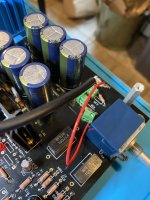
Input at PCB. In this photo the ground wire is mostly hidden by the jacketed cable.
OHHHHH so you DO connect the ground shield on the input side to that point on the board. I was confused because the figure isn't very clear that it should be connected. The text in the build guide just alerts you to the fact that you cannot see it and its not clear that it is connected, so I interpreted that as leave it floating.
@6L6 can you please update the build guide to add this bit of clarity (or I am happy to if I can edit it just let me know how)
As a pretty big noob to all things electronic, obsessed with Whammy (and HPAs) and having built 2, I wasn’t confused by the build guide at all, and you can see the connection with a little selective zooming in for final confirmation.... YMMV.
WAY more importantly—Glad you got it sorted!!!!! How does it sound to you? Definitely read through this thread completely (if you haven’t) and try out opamps. Way too much fun.
WAY more importantly—Glad you got it sorted!!!!! How does it sound to you? Definitely read through this thread completely (if you haven’t) and try out opamps. Way too much fun.
Looks like the missing ground to the board was the culprit. Once I connect the RCA input ground to the board everything works. The preamp is silent without the cap to the ground nut, but I'll add it back when I redo the wiring.
Thanks everyone for your suggestions and help!
Thanks everyone for your suggestions and help!
Attachments
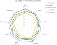
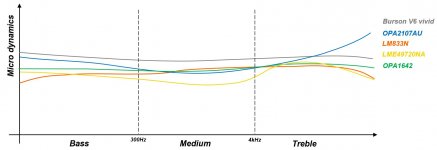
I've been measuring various Op Amps on my Whammy (Burson V6 vivid / OPA2107 / OPA1642 / OPA2156 / LME49720 / LM833N) with Audio Precision APX555.
Detailed objective measurements are available on my blog.
That's my first attempt at using Audio Precision. Any advice is welcome 🙂
Overview:
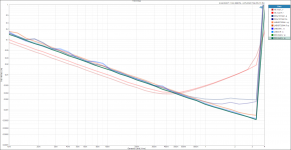
THD = f Hz OP AMPS V2.png (2Vrms output, fixed)
THD+N = f Input Level OP AMPS V2.png (1kHz)
Sighted subjective comparison was also performed. (blind testing still pending).
Benchmar 2020 03 04.JPG
micro dynamics - Op Amp 2020 02 22.JPG
Yes, the V6 burson has higher distortion at highest output levels (above ~5Vrms), which realistically is never used in my case.
I have yet to perform better measurements and identify criteria that could correlate with my subjective impressions.
Detailed objective measurements are available on my blog.
That's my first attempt at using Audio Precision. Any advice is welcome 🙂
Overview:
THD = f Hz OP AMPS V2.png (2Vrms output, fixed)
THD+N = f Input Level OP AMPS V2.png (1kHz)
Sighted subjective comparison was also performed. (blind testing still pending).
Benchmar 2020 03 04.JPG
micro dynamics - Op Amp 2020 02 22.JPG
Yes, the V6 burson has higher distortion at highest output levels (above ~5Vrms), which realistically is never used in my case.
I have yet to perform better measurements and identify criteria that could correlate with my subjective impressions.
Attachments

Last edited:
Okay guys I have spent quite a bit of time and money on obtaining OP Amps for testing and here are by findings:
Dual Op Amps (8P-DIP):
AD823ANZ:
Operating Voltage: 36v MAX
Slew Rate: 22v/µs
DC Offset: L 0.5mV / R -0.2mV
FET: Yes
Notes: Vocals very good but some mids and treble sounds a little raspy.
LM833-N:
Operating Voltage: 36v MAX
Slew Rate: 7v/µs
DC Offset: L -0.1mV / R 3.4mV
FET: No
Notes: Very good all round OP Amp with clear vocals, good soundstage and natural bass.
LM833P:
Operating Voltage: 36v MAX
Slew Rate: 7v/µs
DC Offset: L 22.9mV / R 26.2mV
FET: No
Notes: Very good OP Amp with clear vocals and good soundstage. Improved version of the LM833-N although DC offset is considerably higher.
RC4580 (Texas Instruments):
Operating Voltage: 18v MAX
Slew Rate: 5v/µs
DC Offset: L 14.2mV / R 14.1mV
FET: No
Notes: Good general OP Amp with tiny noticable distortion amounts with certain types of music, sounds best with dance music.
OPA2134PA SoundPlus:
Operating Voltage: 18v MAX
Slew Rate: 20v/µs
DC Offset: L 0.6mV / R 0.4mV
FET: Yes
Notes: Very clear with good soundstage and vocals very pronounced. Very nice OP Amp.
OPA2228PA
Operating Voltage: 18v MAX
Slew Rate: 2.3v/µs
DC Offset: L -0.2mV / R -0.1mV
FET: No
Notes: Very good, clear up front vocals, very good mid and treble, wide soundstage, overall I like this OP Amp.
OPA2107AP
Operating Voltage: 18v MAX
Slew Rate: 18v/µs
DC Offset: L -0.2mV / R -0.3mV
FET: Yes
Notes: Very clear and concise right through all the ranges. Vocals very prominent and wide soundstage. I really like this one.
LME49720NA
Operating Voltage: 17v MAX
Slew Rate: 20v/µs
DC Offset: L 0.8mV R 1.6mV
FET: No
Notes: Nice all round OP Amp with good soundstage. Very clear but mellow sounding.
AD746JNZ
Operating Voltage: 18v MAX
Slew Rate: 75v/µs
DC Offset: L -0.3mV / R -0.2mV
FET: Yes
Notes: Very nice sounding with wide soundstage, clear mids and treble with punchy bass. I really like this one.
LM4562NA:
Operating Voltage: 17v MAX
Slew Rate: 20mv/µs
DC Offset: L -0.4mV / R -1.1mV
FET: No
Notes: Very good all round OP Amp with clear vocals and good soundstage.
NJM4556AD:
Operating Voltage: 18v MAX
Slew Rate: 3v/µs
DC Offset: L 5.8mV / R 5.4mV
FET: No
Notes: Nice OP Amp with clear vocals, wide soundstage and balanced bass. Mids and trebles seem a little softer compared with other OP Amps.
Burson V6 Vivid Dual:
Operating Voltage: 33v MAX
Slew Rate: 45v/µs
DC Offset: L -2.0mV / R -1.5mV
FET: Yes (Fully Discrete)
Notes: Premium OP Amp obviously by far the best I've tried so far. Deep and wide reaching soundstage and up front clear vocals. My number one choice.
Next time I will be testing the following SOIC OP Amps on 8P-DIP adapters:
OPA1622, OPA1662, OPA2210, OPA2189 and OPA1692
Hope some of you find this helpful. 🙂
Do you have options for where to get the Burson V6 Vivid Dual ? None of Mouser, Digikey or PartsExpress stock it.
Thanks!
Hello thomasnadeu,
your search for Burson (if you are in Europe):
Recherche - Audiophonics
Greets
Dirk
your search for Burson (if you are in Europe):
Recherche - Audiophonics
Greets
Dirk
Hi guys,
Been looking to DIY this amp for my headphones. I have some experience in DIY but my electronics knowledge are not great (still learning). Was wondering if anyone made a BOM for Farnell/RSOnline? As where I am located at in Malaysia, these are the only 2 places I can purchase components as compared to Mouser/Digikey as shipping is expensive.
Thanks,
Tee
BOM from Element14
Sorry for double posting. I managed to come up with this. Some resistors I couldn't find exact value so I find a similar one with higher watt. And some capacitors with similar values but different packaging. Not too familiar if all this would have any affects but here I have uploaded the file to show the BOM. Not sure how to copy a saved basket link like Mouser.. So sorry for that..
Apart from this, I bump into an issue where I couldn't find another part that has values close to this. Or rather more accurately I'm not sure if the other LEDs that are close to these values would be suitable.
1. (2) LED D5 D6 {RED} These are not lights, but voltage references use red 604-WP710A10LID
2. (2) 1UF_PP C1 C5 1UF_PP Input coupling capacitor 594-2222-416-71005
Would appreciate any help I can get.
Apart from this, for the pcb, i'm looking for somebody close to me the manufacture it as I have found the gerber files (hopefully I can..). I understand the only difference from that gerber files from the other thread and the one from DIYstore would only be the R39 and R40 (2.2k resistors to the input). Hope someone can verify this?
Thanks! Appreciate all help I can get. 🙂
Attachments
Sorry for double posting. I managed to come up with this. Some resistors I couldn't find exact value so I find a similar one with higher watt. And some capacitors with similar values but different packaging. Not too familiar if all this would have any affects but here I have uploaded the file to show the BOM. Not sure how to copy a saved basket link like Mouser.. So sorry for that..
Apart from this, I bump into an issue where I couldn't find another part that has values close to this. Or rather more accurately I'm not sure if the other LEDs that are close to these values would be suitable.
1. (2) LED D5 D6 {RED} These are not lights, but voltage references use red 604-WP710A10LID
2. (2) 1UF_PP C1 C5 1UF_PP Input coupling capacitor 594-2222-416-71005
Would appreciate any help I can get.
Apart from this, for the pcb, i'm looking for somebody close to me the manufacture it as I have found the gerber files (hopefully I can..). I understand the only difference from that gerber files from the other thread and the one from DIYstore would only be the R39 and R40 (2.2k resistors to the input). Hope someone can verify this?
Thanks! Appreciate all help I can get. 🙂
Look in the forum for discussions around the LEDs including the original build article from Wayne, but the summary is that they provide a steady forward voltage and to not use blue ones (which are noisy). I was looking on Mouser at ordering LEDs yesterday and I know it can be overwhelming (there are 1000s available). What I did was get ones that were as close to those in the build guide as I could, and they work fine.
There were some discussions on the input coupling caps last week on the forum so go back a few pages.
Also I looked at your BOM from the link you showed and I noticed you are missing the chassis safety earth cap (which connects the negative on the inputs/outputs to the chassis). I just ordered a bunch of these this morning from Mouser, so I have the reference handy. Note that I recall the original build has these with lower max V values, but recent discussions have convinced me to use the 450V version "just in case" you have a badly behaving input source.
ECW-FD2W104JQ Panasonic | Mouser
Thanks so much thomasnadeau,
I think I'll just order the specified coupling capacitor (i hesitate because the minimum order from farnell is 10). And thanks for the LED advice + earth capacitor (totally missed it)
After looking through, I realized I'm missing a fuse. If i'm not mistaken I'll need a 250vac 250mA fuse which goes in to the IEC socket?
Also, I realize I need insulators. So will this work?
https://my.element14.com/bergquist/k10-54/sil-pad-k-10-006-to-220/dp/936741?st=insulator
And will using PC thermal grease work? and this would go in between the insulators and heat sink am I right?
Sorry just realize I do not need insulators. and thermal grease between the metal tab regulators and heat sink would be sufficient.
Whammy OCD continues...
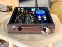
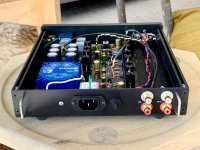
I'm not recommending anyone try this—In my quest for smaller is better... But here's a dead quiet (just the like the first one I made) Whammy in a Modushop 1U Galaxy 230mm square chassis—with blind attached front plate. There was some luck involved here! It's TIGHT in there. —not the kit heat sinks, nor the kit transformer—they are both too tall for a 1U—I think I changed the PSU caps too.
Man I love this amp! Thanks Wayne.
Attachments
Last edited:
Whammy OCD continues...
I'm not recommending anyone try this—In my quest for smaller is better... But here's a dead quiet (just the like the first one I made) Whammy in a Modushop 1U Galaxy 230mm square chassis—with blind attached front plate. There was some luck involved here! It's TIGHT in there. —not the kit heat sinks, nor the kit transformer—they are both too tall for a 1U—I think I changed the PSU caps too.
Man I love this amp! Thanks Wayne.
Your work looks really nice! That chassis is too tight of a squeeze for me though. Mine sits out in the open on a piece of wood until I find a chassis that will be big enough for some things that I'd like to add to mine. Finding chassis for my projects has been difficult for me. Searching ebay and other sites brings up so much random things to sort through it's a chore to look at. I've got an Audio Note Dac kit that I want to move the power supply into an outboard chassis but can't find anything that matches it. I see Chinese chassis that look good for the Whammy but have punch outs and holes that don't match what I need to do. The chassis part of things seems to be the hardest part of DIY. I've still got Aikido preamps and a Millet NuTube buffer that sit open air on wood! I love my Whammy too!
Haha! And some deep knee bends. Thanks Mark!
(I have it on good authority you will stoking my [our!] HPA problem... hopefully ASAP ;-)
Re: chassis @YouAgain/
I would say 6L6’s original build from the guide in the hammond chassis is actually a tighter fit than my 1U. Plus it fits the kit parts in terms of height. The Hammond chassis is nice. All the Modushop stuff is also very nice. I was just tying to pull off a small layout I liked w front power switch and preamp outs and having the pot mounted to the PCB since in the my other Whammy, 2U those signal wires need careful routing for quietness....
Last edited:
Haha! And some deep knee bends. Thanks Mark!
(I have it on good authority you will stoking my [our!] HPA problem... hopefully ASAP ;-)
Re: chassis @YouAgain/
I would say 6L6’s original build from the guide in the hammond chassis is actually a tighter fit than my 1U. Plus it fits the kit parts in terms of height. The Hammond chassis is nice. All the Modushop stuff is also very nice. I was just tying to pull off a small layout I liked w front power switch and preamp outs and having the pot mounted to the PCB since in the my other Whammy, 2U those signal wires need careful routing for quietness....
I want a larger chassis to house a pair of stepped attenuators instead of the ALPS pot that doesn't track left to right well enough for me. I'm sensitive to small level differences and it annoys me if I can't control that. I also want to have space for larger input coupling capacitors and would like to have a switch to choose between two different pairs of coupling capacitors or no capacitor that all. Next is that I plan to use my Whammy to drive a MoFo amp where I'll need the +/- 24 volt rails to make that work (I have the transformer for that). But also want to be able to use input op amps at +/- 16 volts so I'll need outboard voltage regulation (I have super regulators for that) to make that work. Also I have several different flavors of discrete op amps that I use in microphone preamps that I'd love to try in the Whammy. I'd have to build a daughter board to make that possible. Last is I have some good Jensen line input transformers that I want to use to switch the absolute polarity of the input signal. Those can also at the same time provide a balanced input option. So my family of ideas would not fit into the tiny apartment of a chassis that everyone seems happy to build with.
Looking again at your front panel... is that rosewood?
I’d like to see all of that! Mofo is super sweet. On the build list.
Front panel is marble ebony.
Front panel is marble ebony.
Just want to clarify,
The mask file in the gerber file is meant to be used for both the top and bottom layer am i right?
Btw, I'm trying to make 10 pcs of these. So if there's anyone that's interested to buy near where I am, am happy to sell it at cost + shipping and handling. Hopefully this does not violate anything.. Am more than happy to stop if it does..
Thanks!
- Home
- Amplifiers
- Pass Labs
- "WHAMMY" Pass DIY headphone amp guide