I've seen power transformers in some guitar amps where all the laminations were welded to a steel baseplate on two edges. Does anybody know if this is bad practice, or has any effect at all? I was just surprised to see it.
I've seen power transformers in some guitar amps where all the laminations were welded to a steel baseplate on two edges. Does anybody know if this is bad practice, or has any effect at all? I was just surprised to see it.
I'm not surprised. This has become quite common, as it's a good deal easier to weld the lamms than it is to put the E's alternately into the bobbin, then fill the gaps with the I's. If you don't overdo the welds, the very small welds magnetically saturate, but have little effect on the rest of the core. This is just about universal for microwave oven PTXs.
"...this is bad practice..."
It makes it rather inconvenient to take the lamms apart if you want to rewind a dumpster transformer for different voltages.
I think Miles gives the clue.
The very small "area" of the weld in each lamination creates a very small eddy current, i.e. it works.
The very small "area" of the weld in each lamination creates a very small eddy current, i.e. it works.
Peavey guitar amps have welded outputs your talking about. The guitar players like the sound of saturation for more sustain. When it comes to high fidelity this is a no-no . It's a great question, I'd like real answer with graphs and figures.
I specify one weld bead for every lamination stack. This is to guarantee that all lams will remain at ground potential in the event of a wire to lam insulation failure.
The only time I worry about eddies is if a manufacturer chooses to put a bead on both outside edge and inside edge of the same stack, as that creates a shorted turn through which all the flux tries to go. Not bad at DC, but problems as frequency goes up.
As described, two beads on an outer edge will not trap flux, so the only possible issue would be a change in permeability at the bead area.
jn
This is interesting since I have read elsewhere (perhaps on this forum) that resistance between laminations is important, so you would not want to, for example, clean, brush and polish the laminations...
...btw, I have always scratched my head on this idea.
...btw, I have always scratched my head on this idea.
This is interesting since I have read elsewhere (perhaps on this forum) that resistance between laminations is important, so you would not want to, for example, clean, brush and polish the laminations...
...btw, I have always scratched my head on this idea.
They are accurate.
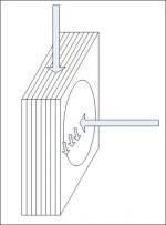
It all depends on the direction of the flux and the way the conductivity is. If the flux is broadside to the laminations, it will eddy big time My pic has it with flu from the right.. If it is goes the same direction as the length of the lams (coming in from the top), the conductivity is broken up by the insulation between the laminations. I use a glue, it takes up about 2% of the volume of the stack.
If you remove the glue or layer to layer insulation, then eddies can occur with respect to the flux coming in from the top in my picture.
jn
Attachments
This is fascinating, I just looked at my MOT transformer Im working with & sure enough it is not alternate EI stacking. I have two 10mH 100W coils I can easily unwind to wind the secondary. Another thread is running now about MOTs for B plus tube supplies....this ties in perfectly...I was contemplating hammering out the shunt stacks when I noticed how easily it can rip up the fabbed cardboard bobbin. Cutting out the welds will be so much easier & Ill have access to everything................Now....getting the turns right for my 220-230 VAC....??
______________________________________________________Rick..........
______________________________________________________Rick..........
While it's apart you may find a way to add on 20 or so extra Primary Turns and find room for the very necessary insulation.
The difference this makes to the idling current is quite high and it certainly reduces operating temperature.
The difference this makes to the idling current is quite high and it certainly reduces operating temperature.
Magnetic flux takes the path of least resistance just like electric current. So welding near the outside of of a turn in the magnetic path doesn't usually cause unacceptable loss. This "outside of a turn" also occurs in the middle of the center pole too, and is why the "nick" in the middle of the E's and I's for accomodating a mount bolt makes almost no difference in magnetic performance. Also, in output transformers a minor gap formed by non-interleaved laminations is not necessarily unacceptable either. The weld might become fairly saturated at high throughputs but it's such a small portion of total core volume it usually will not break the design. The welding is mostly done as a cost savings even though most power transformers are interleaved by machine, but it does yield a very strong mechanical assembly especially with the addition of varnish impregnation, which can really hold down mechanical noise, which is always a problem in gapped transformers run hard.
For my applications, we purchase lamination stock which already has a coating on both sides of the laminations. We use two different methods to make our cores:
1. Stack laminations to the desired thickness, then cure in an oven at rather high temperatures while the stack is in compression. Once done, the shape of the final core can be either machined, or wire EDM'd.
2. Stamp the individual laminations to the final shape, then stack and cure them in the oven. Then, if accuracy is required, further EDM can be done.
But both cases require high temperature. I suspect that interleaving the E/I's through the bobbin, then curing it, may be too much for the bobbin to handle, or even the insulation of the wire. So I suspect most of the cores out there will not be interleaved, especially if they don't want lamination noise.
edit...ah, I didn't consider varnish impregnation of the entire core as well...my app, the varnish would not survive the x-rays.....AndrewE, Andrew T... nice comments..
jn
Last edited:
So we will be dealing with so-called issues, same as the cut C core......trying not to be a so so gapped TX. Alignment should be no problem as the lams are factory cut. I will have to dress the area of removed material making passes with a fine file....With the grain....or lams as it were.I could fab up some sort of framework to apply pressure holding it together...& lined up....HHmmmmm? I do hope the ...I lams dont fall apart when it comes off but experience tells me NOT EVEN taken more than a few apart by now.
I would like to re-insulate & dress this up before re-assembling, after all it will be up top on my amp....I have some hi-temp gloss black spraypaint.....
____________________________________________________Rick..........
I would like to re-insulate & dress this up before re-assembling, after all it will be up top on my amp....I have some hi-temp gloss black spraypaint.....
____________________________________________________Rick..........
Since the I's are going to be intact, I could wind the entire assy with the 18 gauge I have from the pair of coils, 18G, 10mH, 1.95 ohm Rdc. This gauge is slightly smaller than the primary....could I use this as primary so the massive present primary won't have this big idle?
I will wind all of the secondary(Hoping it's below my primary 220VAC) & start removing turns OR did I get that backwards.......
I will have to come up with a protocol for this testing of secondary output voltages......still thinking this one thru.( Can't upload PIX for that silly security token thing)
_________________________________________________________Rick.....
The weld in the corner of a rectangular lamination is practically outside the main flux path, which as we all know is curved (the justification behind C cores) so it has nil effect, if any.
FWIW the main reason behind welding transformer laminations to an 1/8" iron baseplate is for strength of mounting, something always importan in the Peavey world 🙂
FWIW I *glue* (with contact cement) my transformers to the mounting surface, besides bolting them down, of course.
Long time ago I did sometimes get amps for repair with loose or even flying transformers, because of lost nuts, cracked legs or both.
Imagine an elephant in a bazaar or the origin of the term "loose cannon" but in the last 20 years (after gluing) it never happened.
In fact, the few times I had to replace a burnt transformer it was quite hard to pull it away.
Just to note for the OP, in the case of a non-interleaved welded core the permeable weld material does bridge the gap at the edges, which might cause a "strange" BH curve with the weld material causing an increase in inductance at low levels and saturating through the linear range of the rest of the core. I don't think it would be something to do for audiophile output transformers though it might not figure in too much for guitar amps.
Wow, great answers and depth- thanks! Though I've spent a lot of time fooling with switching transformers, I'm pretty much an off-the-shelf 60 Hz transformer user. Have to agree, welded would be a pain to rewind.
I asked the same question a few months back after the large output transformer broke its welds and took out all the tubes in a Peavey VB-2 bass guitar amp.
I asked the same question a few months back after the large output transformer broke its welds and took out all the tubes in a Peavey VB-2 bass guitar amp.
Ouch !! 😱
I don't even want to Oimagine* the abuse that head must have gone through .
If ciurse, very strong does not mean indestructible 🙁
- Status
- Not open for further replies.
- Home
- Amplifiers
- Solid State
- Welded transformer stack- good, bad?