Havent tried it yet. Will do once I get home and will post the result here.
Thank you for the suggestion.
Thank you for the suggestion.

A-B inductance is zero (0.000) on my LCR meter not Ø, as it tries to measure it but it settles on 0.000. A-B resistance is 0.6 (sometimes 0.5) ohm.
B-B1is null/Ø - cannot be measured because they are 2 diferent wires.
B1-C is 211mH and 0.7(sometimes 0.8) ohm.
B-C (B and B1connected/shorted) is also 211mH but 0.9(sometimes 0.8) ohm.
A-C (without B and B1 connected/shorted) is null (Ø), cannot be measured because they are 2 diferent wires.
A-C (B and B1 connected/shorted) is 0.580mH and 1.2 ohm (sometimes 1.1)
The two windings are the same gauge.
According to these measurements, the inductance between A-B should be around .09mh, or 40% of the total windings. B-C is .211mh, or 60% of the windings. A-C with B and B1 connected is .580mh, or 100% of the windings. I'll assume the driver is connected to B and C, and the input voltage is connected to A and C. The voltage across B-C would be down 4.4db.
Attachments
Kinda like this? I took a wild guess on the driver impedance's and the woofer inductor. I know the inductance between A and B-B1 is still a mystery.
.png")
Yes.
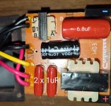
You can see the layout of the pcb in my first post.
Yellow wire is the + tweeter and the red ones are the woofers +
You can see the layout of the pcb in my first post.
Yellow wire is the + tweeter and the red ones are the woofers +
Would you say that mboxler has introduced the idea that other components may be interfering with the measurements?
So it would appear that the coil A-B exists and is not normally shorted. It wouldn't necessarily need to have a lot of turns to produce this effect.Actualy, yes. I get 0.000 mH and about 0.6 ohm.
There are no components to interfere with the measurements. The coil/autotransformer is out of the pcb. The photos of the pcb and crossover are of the other speaker which is in its original state.
When A-B is shorted, B1-C behaves just like A-B when are not shorted, 0.000mH with "some" resistance.
A-B is the first wire of the coil, B1-C is the second one. A-B has continuity, just like B1-C. A-C has no continuity unless B and B1 are shorted.
When A-B is shorted, B1-C behaves just like A-B when are not shorted, 0.000mH with "some" resistance.
A-B is the first wire of the coil, B1-C is the second one. A-B has continuity, just like B1-C. A-C has no continuity unless B and B1 are shorted.
Do you have a spare inductor? To verify the measurements, connect it to A and C and connect B to B1. Your parallel measurement between A - C should now be less than .580mh and one can then verify that A - C is truly .580mh. You can also connect the inductor to A - B to see if you still get zero inductance.
It would be a pain but interesting to measure the coils on the other speaker.
It would be a pain but interesting to measure the coils on the other speaker.
Last edited:
I have the woofers inductor, it only has a single wire with "just" 2 ends. 🙂 I'll refer to them as X and Y.
How should I connect A, B, B1, C, X and Y?
How should I connect A, B, B1, C, X and Y?
Connect A - X and C - Y. Connect B - B1. The woofer inductor is now parallel with the entire .580mh coil.
Woofer inductance is 0.770
A-X and C-Y (B and B1 shorted), basically a closed loop, is 0.290 mH, 0.2-0.3 ohm.
A-Y is 1.420 mH, 1.4 ohm
A-X and C-Y (B and B1 shorted), basically a closed loop, is 0.290 mH, 0.2-0.3 ohm.
A-Y is 1.420 mH, 1.4 ohm
Woofer inductance is 0.770
A-X and C-Y (B and B1 shorted), basically a closed loop, is 0.290 mH, 0.2-0.3 ohm.
A-Y is 1.420 mH, 1.4 ohm
Hmmm. A .77mh in parallel with a .58mh should equal .33mh. .29mh is low but close.
Don't understand the 1.42mh measurement. A - Y should be the same as A - C (.29mh)???
Sorry for the wild goose chase. I'm just trying to verify the accuracy of your meter when measuring the autotransformer. Still stumped.
I can think of two more ideas...
1) Remove and measure the mysterious coil in the other speaker
2) Do a voltage test on the one you have already removed. You would need an AC voltage meter and a way to generate a fixed frequency voltage across A - C, then measure the voltage across BB1 - C. That would nail the turns ratio. I'd use a capacitor on the input side and a resistor across BB1 - C on the output side. I wouldn't turn your amp up any higher that 1 volt across A - C.
The zero inductance of A - B is too weird.
- Home
- Loudspeakers
- Multi-Way
- Weird crossover coil