another view of it: china steals left and right what the west does. if you even dare to have some product made in china, you can COUNT on it being ripped off. is there anything you can do? NO. nothing at all. they get away with it and laugh in your (virtual) face.
so, turnabout might be fair. why respect them if they don't respect you? maybe if enough of their 'designs' were stolen they'd start to think twice about the same treatment to us.
its currently asymmetrical and I see no sign of china respecting our IP. so I say, don't respect theirs. fair is fair. if they want to play that game, play it back.
Yeah, that's great info thanks. I'd have been pretty huffed off with that speaker situation!
I was just assuming as they're selling these dacs as un-housed boards that they were free to use in bigger prodcuts
I was just assuming as they're selling these dacs as un-housed boards that they were free to use in bigger prodcuts
haha nice point there. I was mulling this over when thinking about getting my sensor device made over there. once they have your gerbers obviously they can enter your market (minus the source code in your MCU which they'd have to come up with).
That is what I am into: speakers. I'm skilled with vacuum tubes, but solid state tends to be quite a different animal to tame, and I am taking it one day at a time. If I designed my own DAC board, I would implement my own analog filter, I/V stage, and line level amplifier to suit my goals. That might be a path for you to take. Or, you could partner up with someone who is quite savvy with those aspects of design to help you. When you design something and know its limits, you do not have to worry about other mistakes haunting your project.
haha nice point there. I was mulling this over when thinking about getting my sensor device made over there. once they have your gerbers obviously they can enter your market (minus the source code in your MCU which they'd have to come up with).
for group buys or one-offs, sending gerbers there might be ok.
if you are going to build something to sell and you care about stolen IP from you, no way in hell would I send anything to china to have it made. I'd take my lumps and pay western labor rates, account for it in the product price and go that route.
yeah, the sensor device is not cutting edge so not too fussed.
How about you send the tracks and the drill files to a PCB company, then the solder / fiducial template without the PCB tracks on it to a seperate assembler, and program the chips yourself. Then both only have 1 piece of the 3 piece puzzle?
How about you send the tracks and the drill files to a PCB company, then the solder / fiducial template without the PCB tracks on it to a seperate assembler, and program the chips yourself. Then both only have 1 piece of the 3 piece puzzle?
yes, it could work that way. if no one has the full picture of how to build the product, you have at least some chance that it won't be copied and sold outside of your own channel.
I'd rather try to charge a bit more (and explain to the customers why) and then have it all done in the west. if its an upmarket device, that could actually work in your favor.
I'd rather try to charge a bit more (and explain to the customers why) and then have it all done in the west. if its an upmarket device, that could actually work in your favor.
Yeah that is obviously the better way. It is a slight niggle that so many electronics are so extremely cheap these days. It means that knowledge in an extremely technical subject and skills to produce products does not always pay well.
I guess it's all down to markets but spoilt for choice consumers are used to paying peanuts for most things.
I'm sure with enough market experience it's possible to choose the right path's that make for good returns.
I guess it's all down to markets but spoilt for choice consumers are used to paying peanuts for most things.
I'm sure with enough market experience it's possible to choose the right path's that make for good returns.
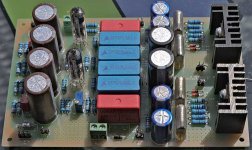
I have found that the board, as well as the dac7, have been made such as to resemble an arcam circuit, thought that was interesting anyways after messing with this for well over a year now.
Some of the Chinese auctions had shown this, and when I looked a bit at some of the arcam boards, I could see how this would be true.
Some of the Chinese auctions had shown this, and when I looked a bit at some of the arcam boards, I could see how this would be true.
I have a v.1.9 of the dac5 bought as a kit from Weiliang (without the USB board) and am after some help in debugging it. As recommended when @bcmbob was working on his, I've checked the outputs of all of the voltage regulators and they're all fine. However, the only sign of life that I get is the power LED - I've tried driving it with both optical and coax inputs but I hear absolutely nothing. (I've tried toggling the input selector switch, again to no avail.)
From posts earlier on this thread I realised I'd mounted the oscillator round the wrong way (it was getting very hot). I've now got it orientated correctly but nothing obvious has changed so I'm thinking about the next step. First off, I'm wondering whether I could have broken the oscillator by having it the wrong way around. Does anybody know?
From posts earlier on this thread I realised I'd mounted the oscillator round the wrong way (it was getting very hot). I've now got it orientated correctly but nothing obvious has changed so I'm thinking about the next step. First off, I'm wondering whether I could have broken the oscillator by having it the wrong way around. Does anybody know?
I think a burned out oscillator is a good guess. What test equipment do you have available?
I have a v.1.9 of the dac5 bought as a kit from Weiliang (without the USB board) and am after some help in debugging it. As recommended when @bcmbob was working on his, I've checked the outputs of all of the voltage regulators and they're all fine. However, the only sign of life that I get is the power LED - I've tried driving it with both optical and coax inputs but I hear absolutely nothing. (I've tried toggling the input selector switch, again to no avail.)
From posts earlier on this thread I realised I'd mounted the oscillator round the wrong way (it was getting very hot). I've now got it orientated correctly but nothing obvious has changed so I'm thinking about the next step. First off, I'm wondering whether I could have broken the oscillator by having it the wrong way around. Does anybody know?
By the way, a couple of days ago I connected a 6N16B-based amp and cathode follower to the output of the WM8741 in place of the op amps I was using (LME49860 AND 49870) in my DAC5. My opinion is that the sound improved quite a bit. The tube amp is a Barbara Gerhold design.
RuSubMin-Audio
RuSubMin-Audio
Attachments
I have a multimeter and a hantek 2150 DSO. However I'm not too confident in the scope -it's about 20yrs since I last used one. I'll order a new oscillator and see what happens. ..
I recall that the optical input was a bit particular as to what would actually pick up and make sound, might want to try several sources before you give up.
The TE7022 boards are extinct, have been replaced with SA9023, and is better sounding, much less prone to ESD damage.
The TE7022 boards are extinct, have been replaced with SA9023, and is better sounding, much less prone to ESD damage.
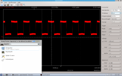
So, I've checked the input voltage to the oscillator (4.95V) and scoped the output of the oscillator (see attached pic). The latter is confusing as it appears to show that the output has period ~24uS whereas I think I'm expecting ~0.1uS. When I next get the chance I'll check the scope against its built-in signal generator and also try reducing the time base when looking at the output of the oscillator.
While I'm here, does anyone have the schematic of this board that they could send me privately?
While I'm here, does anyone have the schematic of this board that they could send me privately?
Attachments
Google"audio-talk wm8741 eBay", and you will see a thread named" another eBay dac", or something like that. A few posts in you will find a link to a .pdf, copy it and keep it in a safe place...
Thanks phase - I found it. I've replaced the oscillator and things have improved somewhat: the spdif LED now lights-up when I connect (the digital output from my DAB tuner) to the coax. input. The toggle switch between USB/spdif input also causes this LED to go on/off as appropriate.
However, there is still no output of any sort :-( I haven't managed to find a cable to test the optical input yet - need to go up in the loft and look through some boxes.
However, there is still no output of any sort :-( I haven't managed to find a cable to test the optical input yet - need to go up in the loft and look through some boxes.
Hello, were you able to resolve the issue of crackling (huge bang) when changing sampling? this is very annoying
I have dac7 + cm6631a. when, more than once I change songs in jriver I have crackles (songs are sampled differently).
I have dac7 + cm6631a. when, more than once I change songs in jriver I have crackles (songs are sampled differently).
Have been using mine daily now with an SA9023 usb interface, with standard windows 10 audio player for years. I don’t have any experience with jriver however.
Man I got a balanced weiliang amplifier and it was awful. The 4-pin XLR was out of phase the and the L/R markings were reversed on the case. It's a pity as it actually sounded great on SE.
Other sellers have it with different musese opamp options and Nobsound have a re-branded one.My amp making friend pointed out ti was a motorized pot but wasn't hooked up. If someone could get the schematic of this and fix the issues you'd have your self one hell of an amp as it's SE power may have exceeded my THX789 balanced which is 6 watts @ 32ohms.
Assemble E600 Fully Balanced Input Balanced Output Headphone Amplifier +Case | eBay
Last edited:
- Home
- Source & Line
- Digital Source
- WEILIANG DAC5 - WM8741 & Tenor TE7022